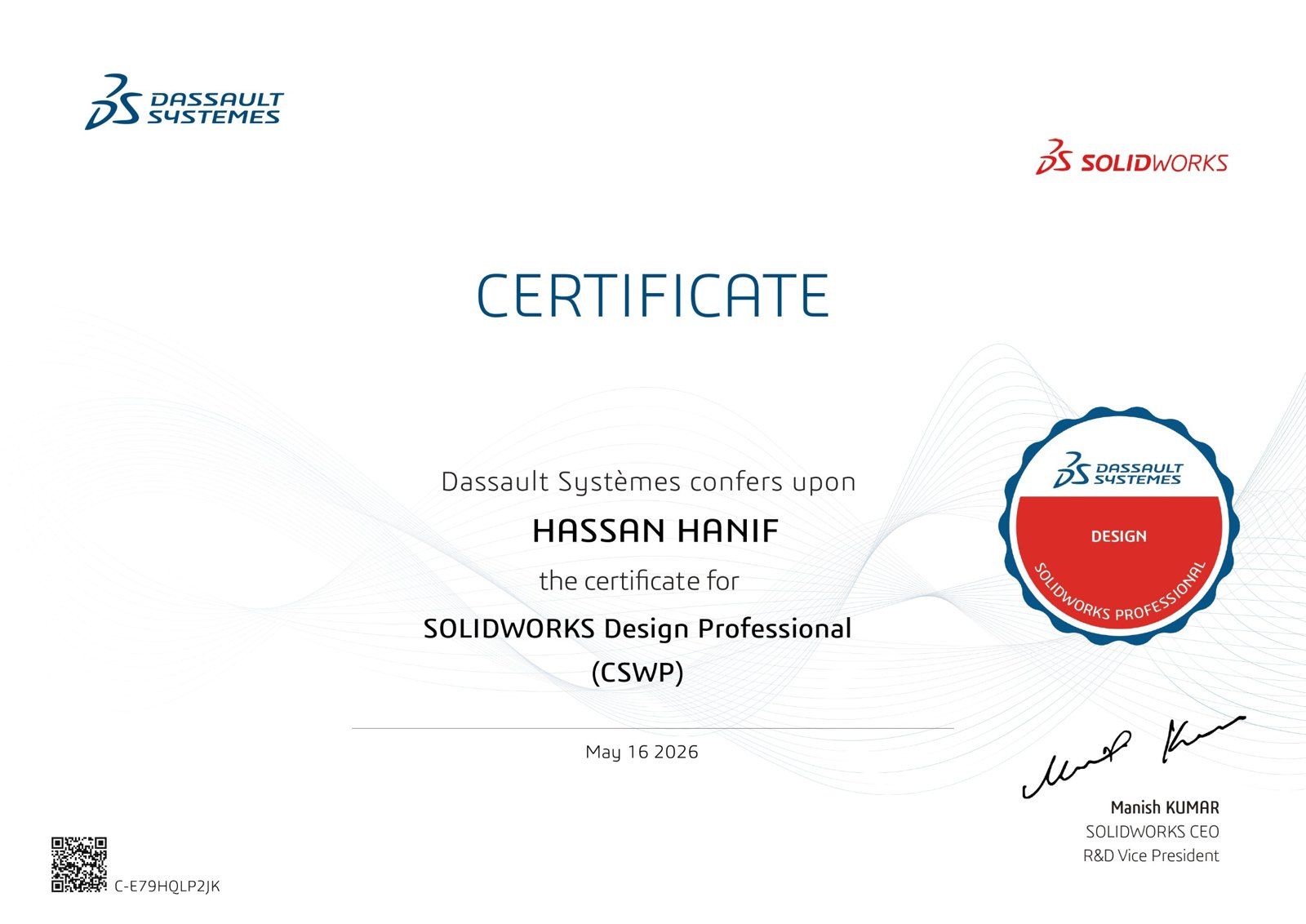
SOLIDWORKS Design Professional (CSWP)
Dassault Systèmes · May 2026
Mechanical Design Engineer for product development, CAD, and manufacturing
I turn engineering concepts into practical, manufacturable designs: 3D CAD, mechanical assemblies, reverse engineering, manufacturing drawings, sheet metal, structural fabrication, and CNC-ready files.
✓Certified SOLIDWORKS Professional (CSWP) ★Top Rated on Upwork · 100% Job Success
I hold a Bachelor of Science in Mechanical Engineering from HITEC University, Taxila, Pakistan. My experience covers mechanical design, component and assembly modeling, engineering documentation, fabrication-oriented design, and coordinating mechanical design work.
I have worked on everything from individual components and detailed assemblies to structural frames, sheet metal parts, CNC-cut components, and product prototypes.
I focus on more than the 3D model. I consider how a product will be manufactured, assembled, maintained, and used, so clients can move from an idea to a manufacturable solution. I am building my independent practice through H2 Design Agency, serving clients internationally.
Each service comes with real work from my portfolio.
CAD rebuilt from existing parts, meshes, STL or OBJ files, or scan data, depending on source quality.
Includes: mesh-to-CAD, surface modeling, parametric models, STEP exports.
One of my main reverse engineering projects. A wooden puzzle box with its whole mechanism hidden inside. I used CT scan slices to see every internal part, rebuilt the full mechanism as a SolidWorks assembly, and the client then 3D-printed a working prototype from my model.
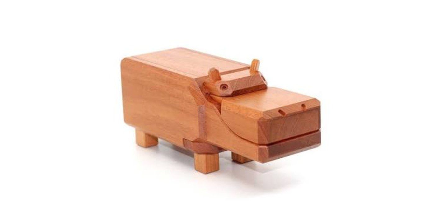
1. The original puzzle. A wooden puzzle with its mechanism hidden inside.
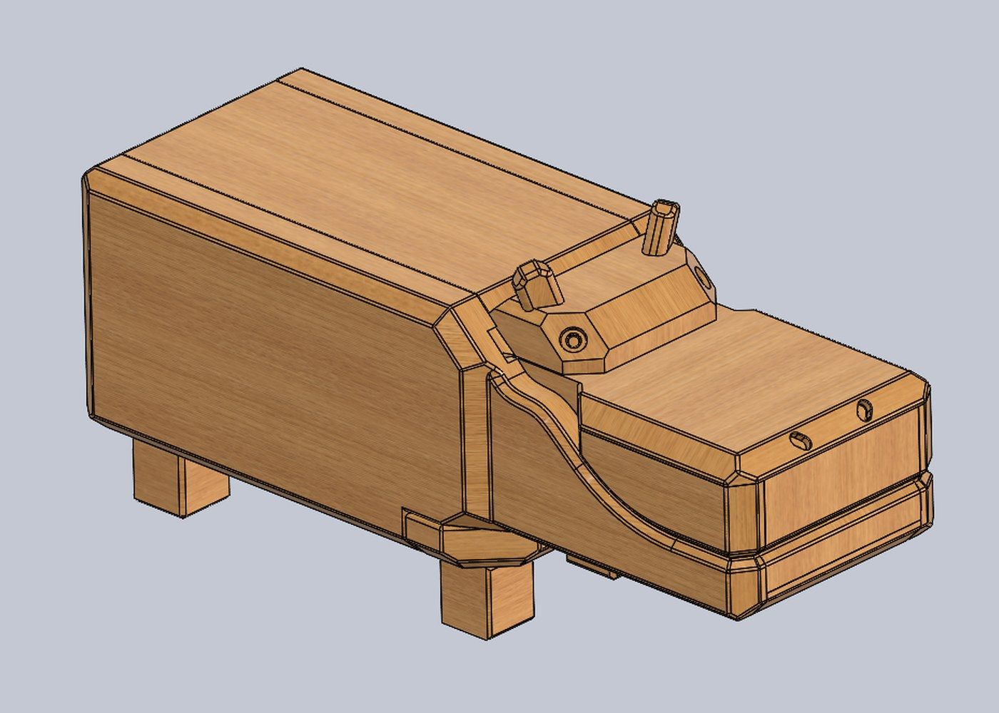
3. CAD model. The full puzzle rebuilt in SolidWorks.
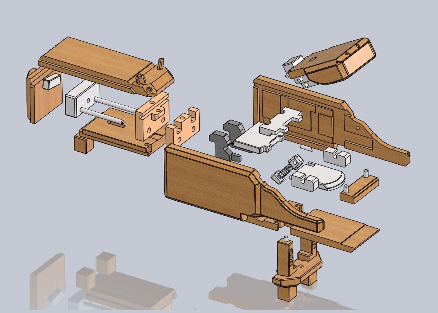
4. Exploded assembly. Every internal part, shown separately.
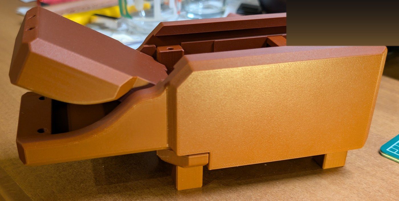
5. The 3D-printed prototype. Printed by the client from my model, with the jaw open.

 CT scanCAD section view
2. CT scan to CAD section. Drag the slider. The CT slice and my CAD section view are in the same orientation, so you can see the hidden jaw, latch and spring turn into clean parts.
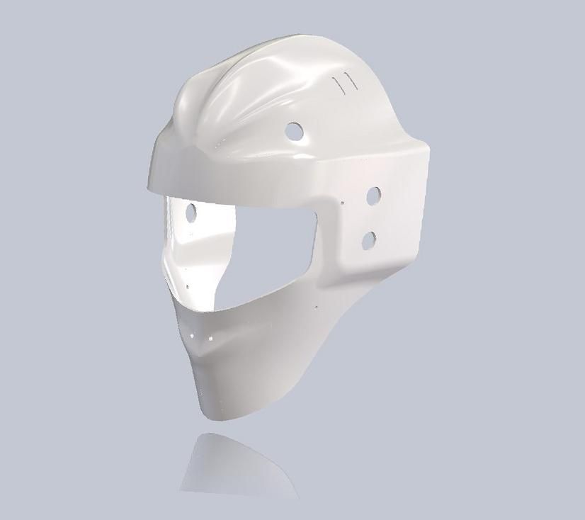
 STL inputSolid CAD
Drag the slider to compare. A rough STL mesh rebuilt into a clean solid body with surface and solid modeling, ready for modification or reproduction.
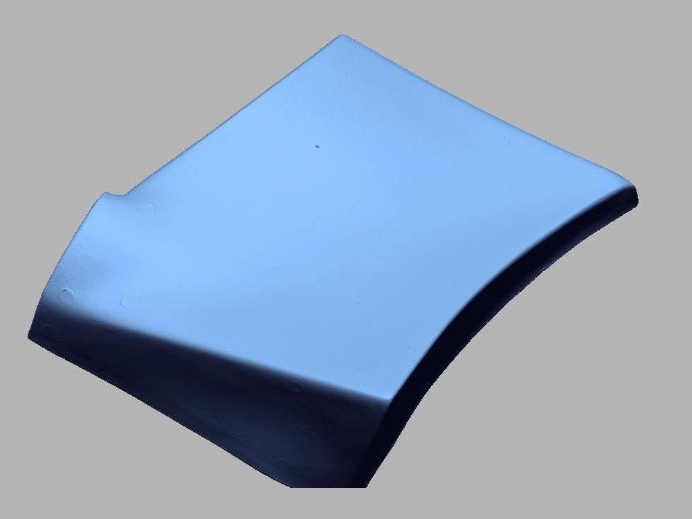
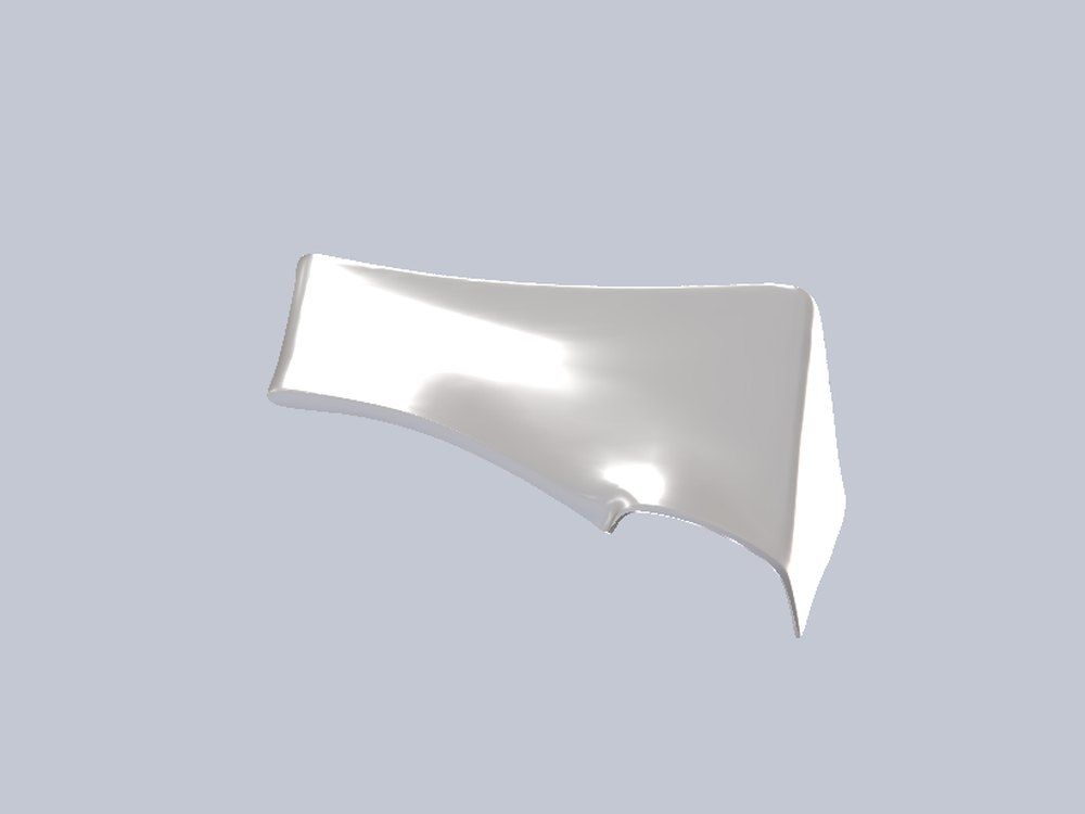
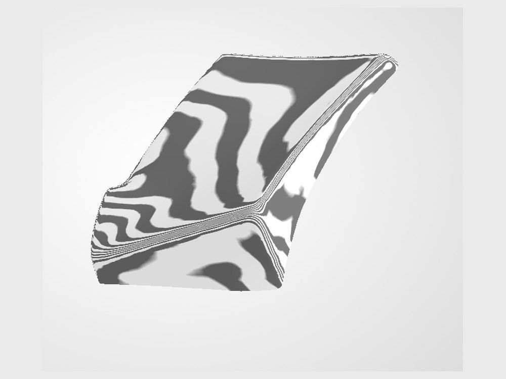
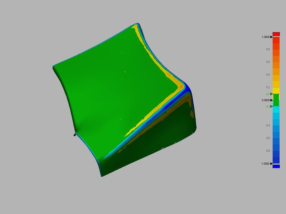
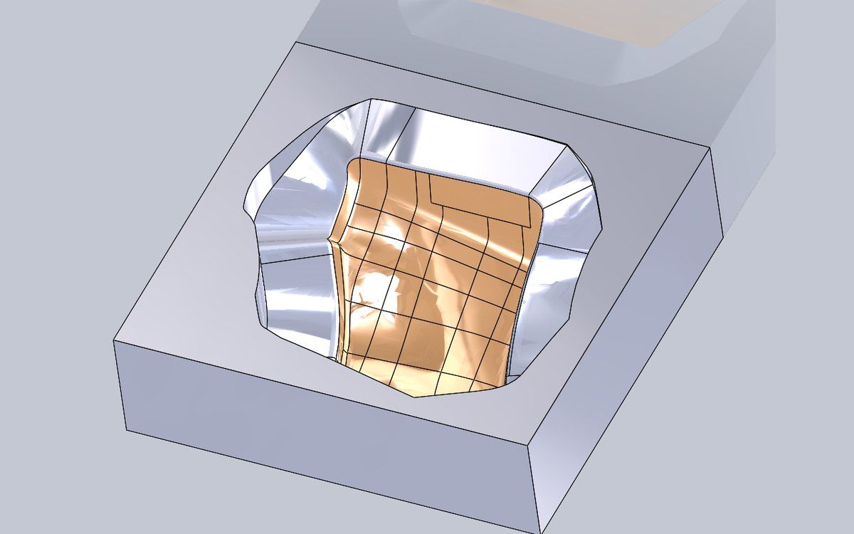
A scanned fiberglass automotive body panel rebuilt as a smooth, clean solid body with no visible surface marks. The surface was checked with zebra analysis for continuity, and compared with the original scan on a ±1 mm deviation map. Only one tapered edge shows a slight deviation. I also designed a tooling block, with a cavity matching the panel surface, for layering the part.
Fabricated assemblies for industrial applications.
Includes: welded frames, machine frames, chassis, tube-frame assemblies, weldment drawings, cut lists.
 RenderSolidWorks model
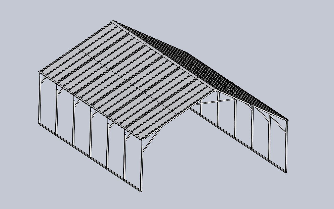
A complete steel parking canopy, taken from concept to production-ready documentation. Built around standard structural profiles that can be sourced in the client's region, with connections, cut lengths, and exact hole sizes and positions defined for fabrication. Drag the slider to compare the render with the SolidWorks model.
Use Previous / Next to flip through the sheets. Click a sheet to enlarge. Dimensions, hole sizes and hole positions are called out on every part, drawn in inches to ASME Y14.5M-1994.
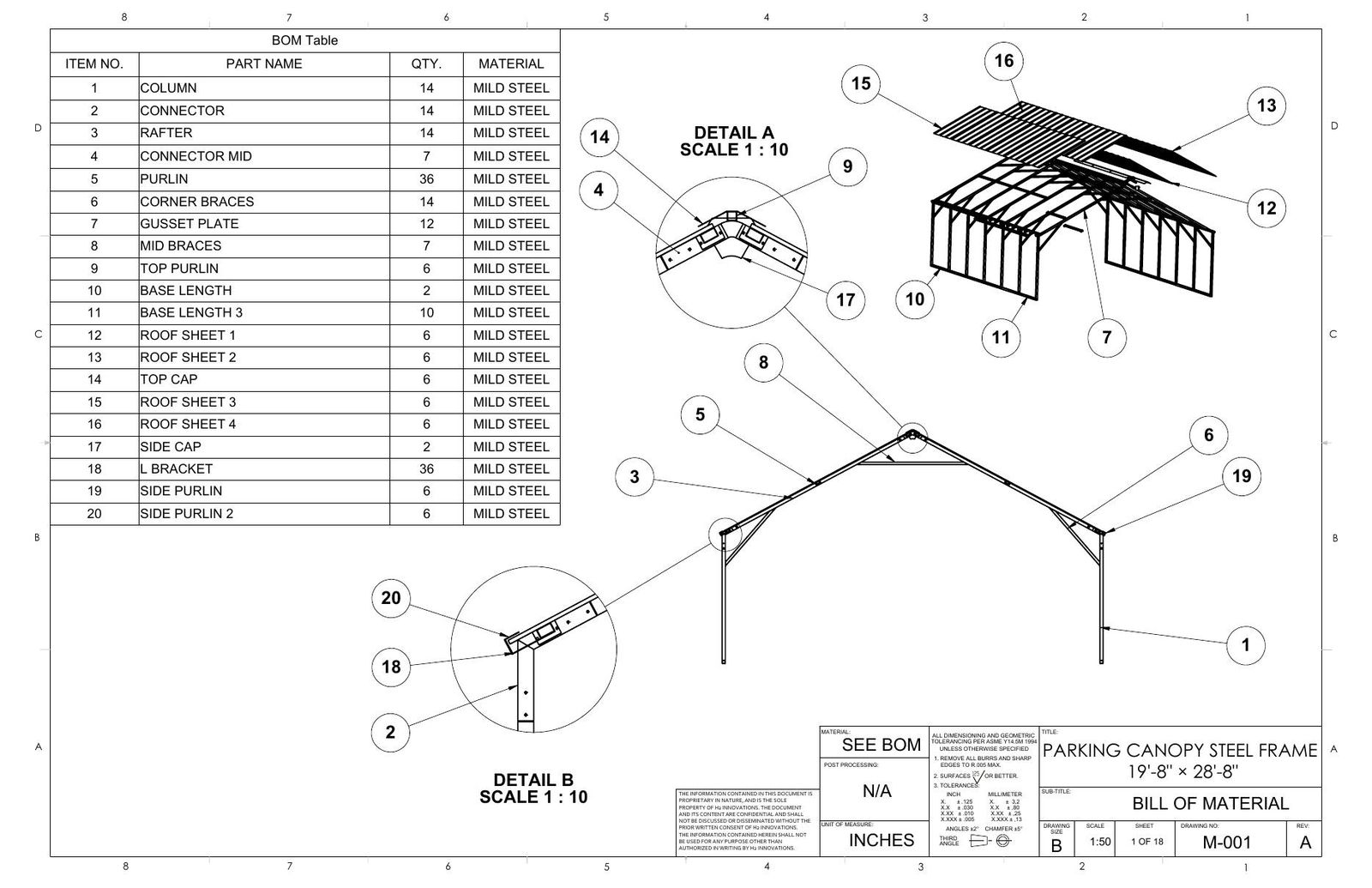
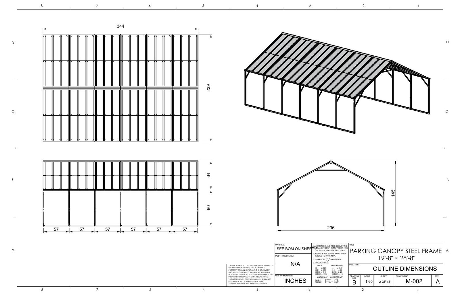
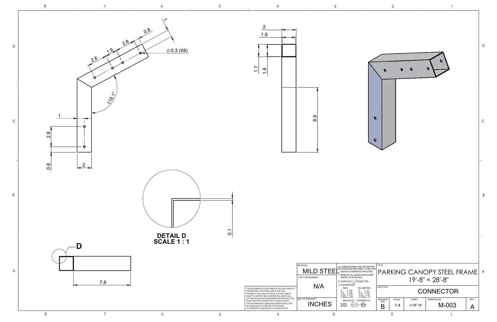
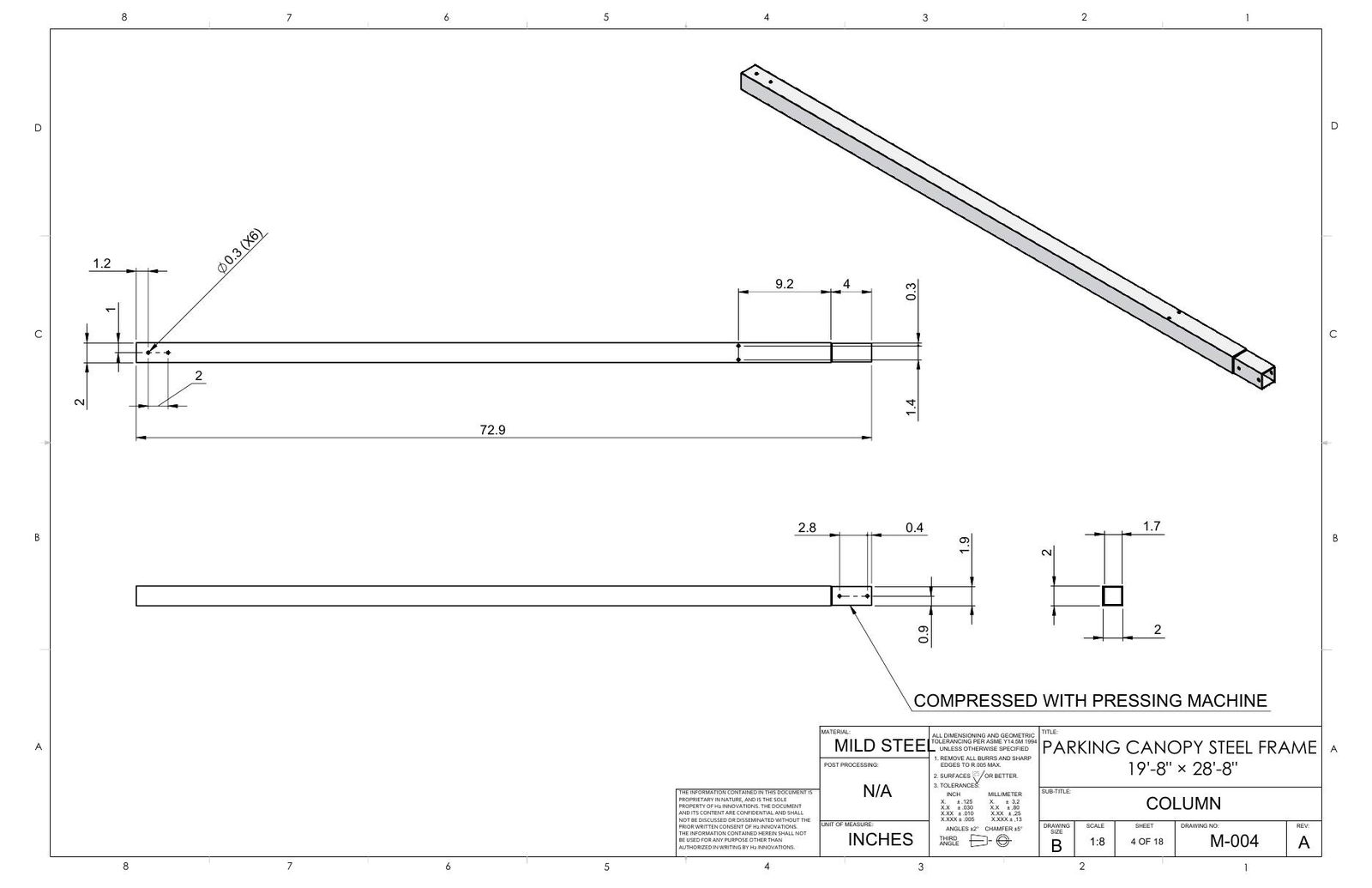
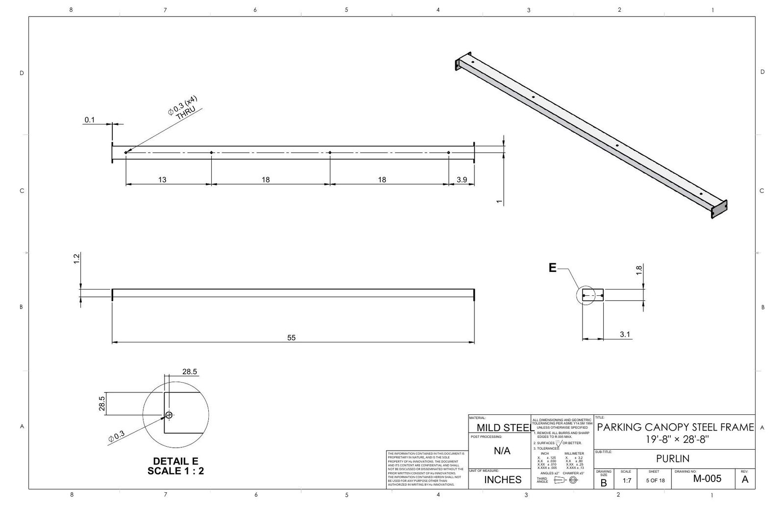
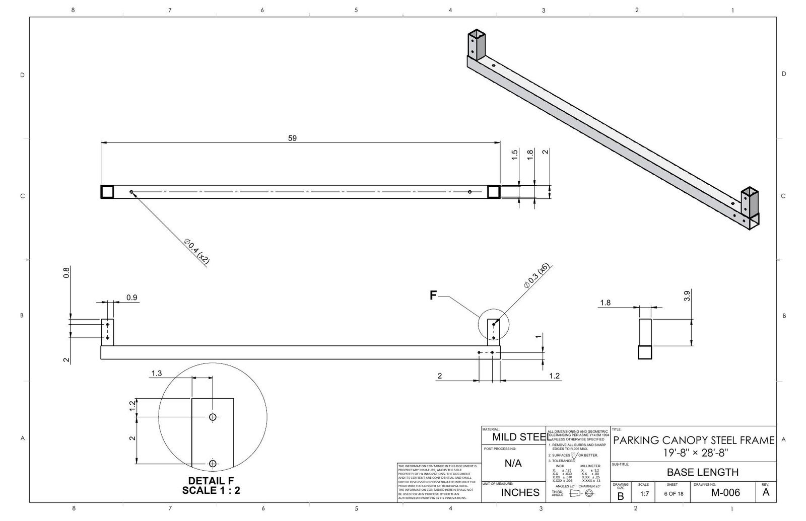
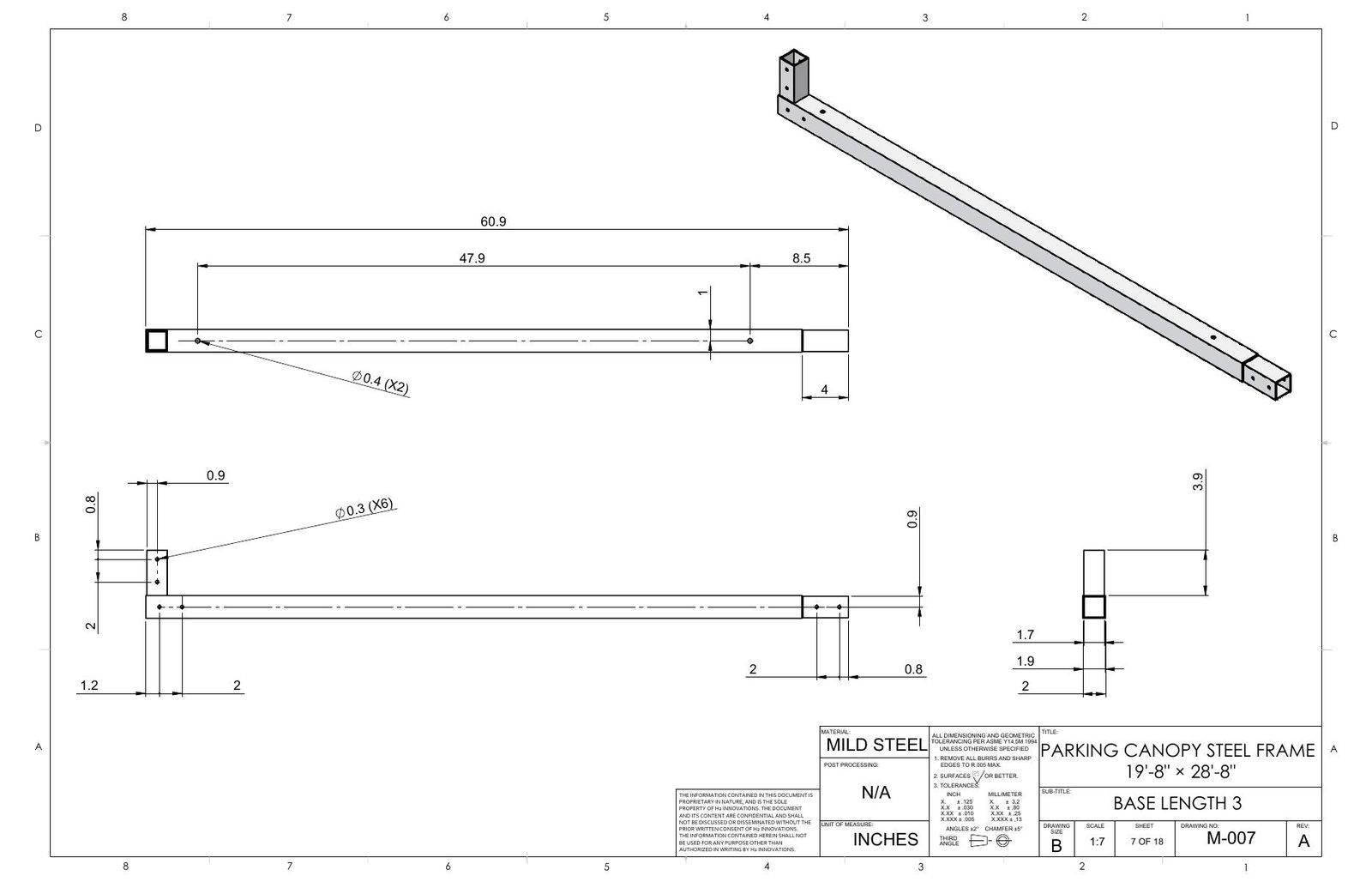
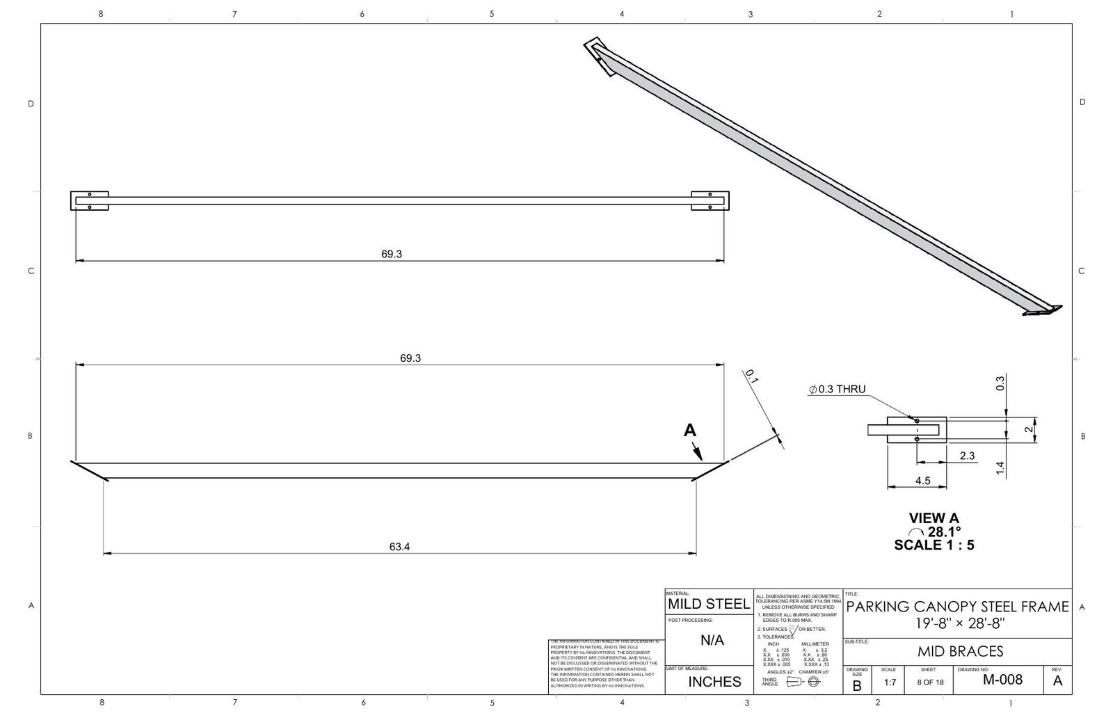
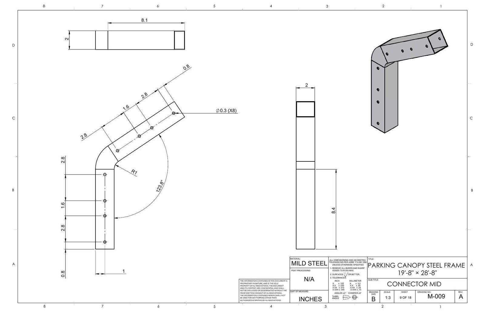
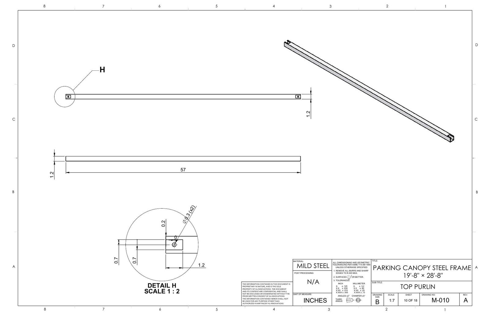
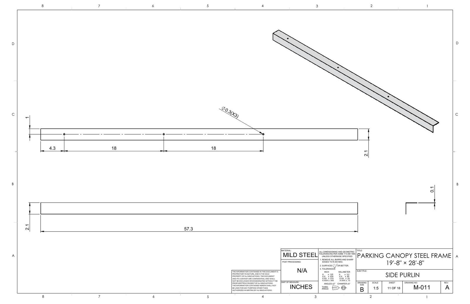
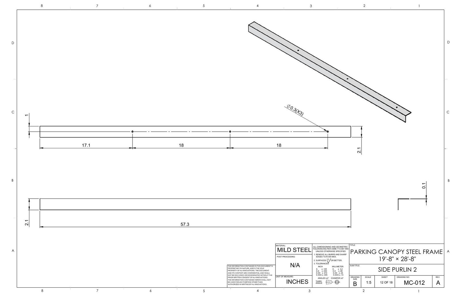
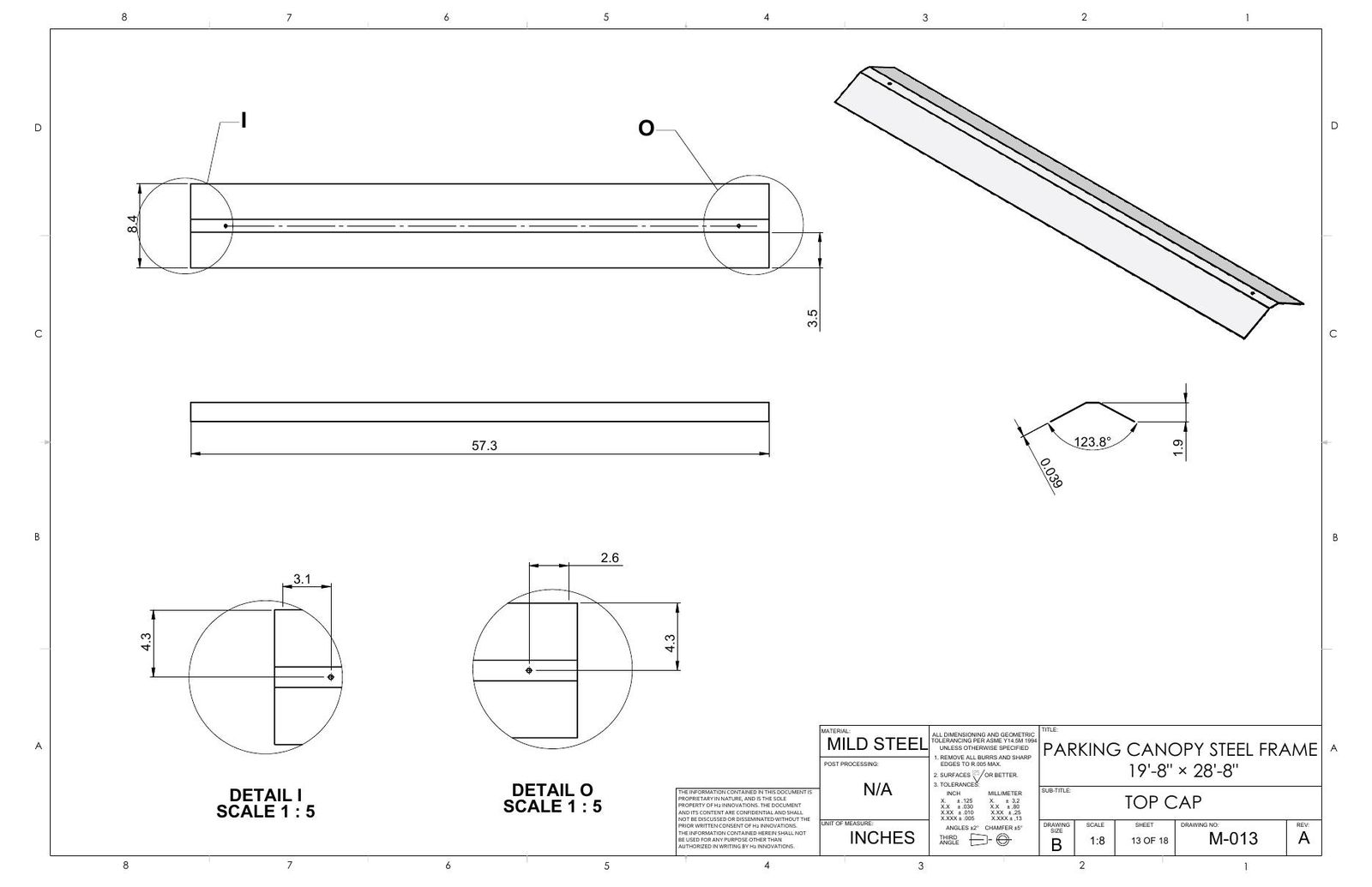
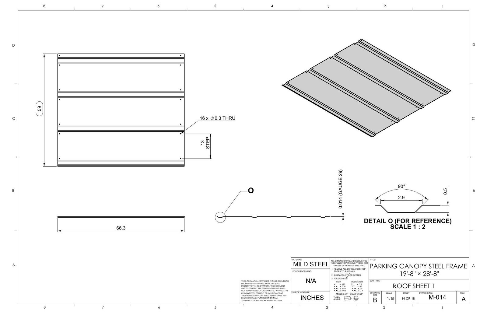
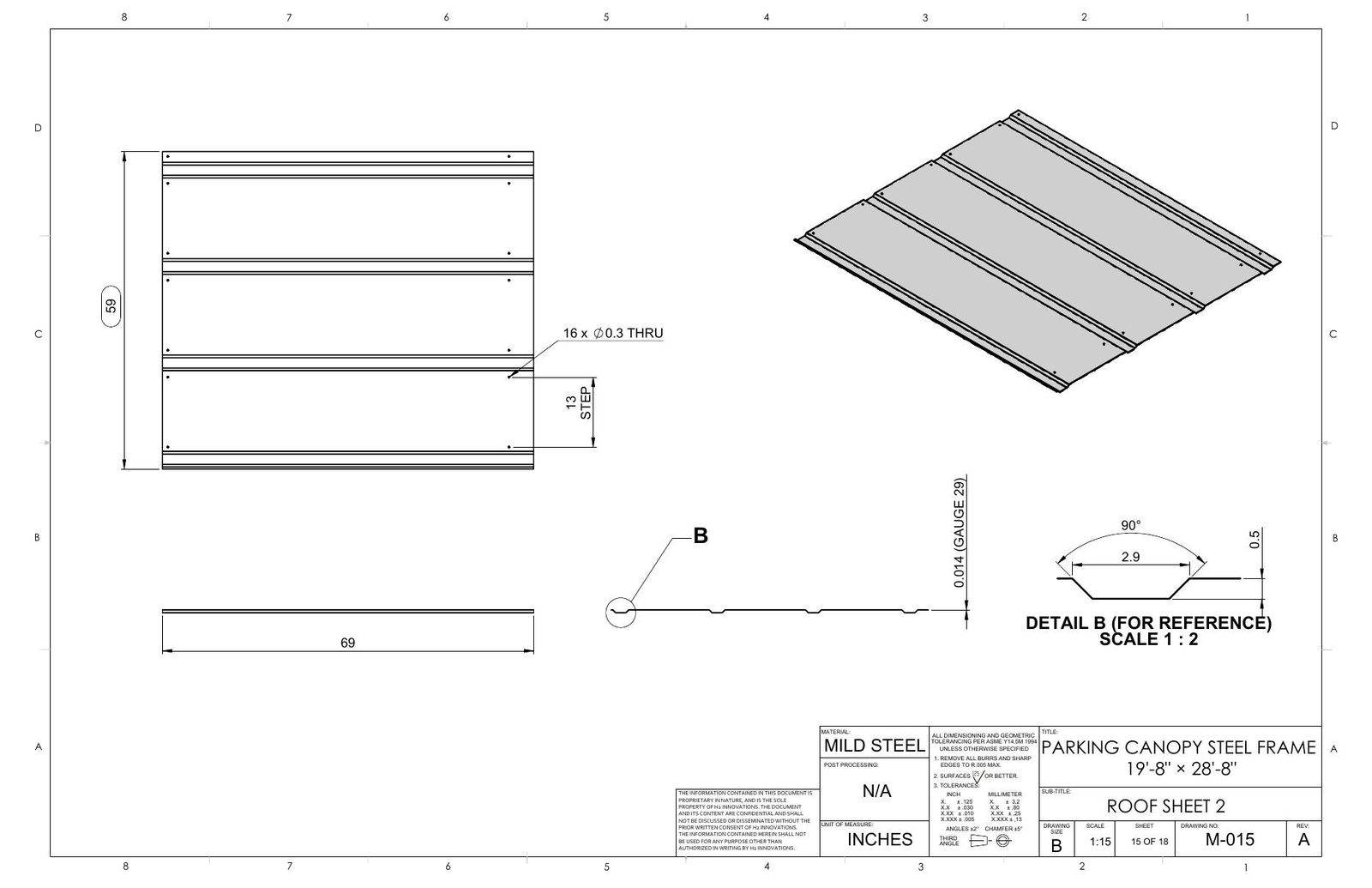
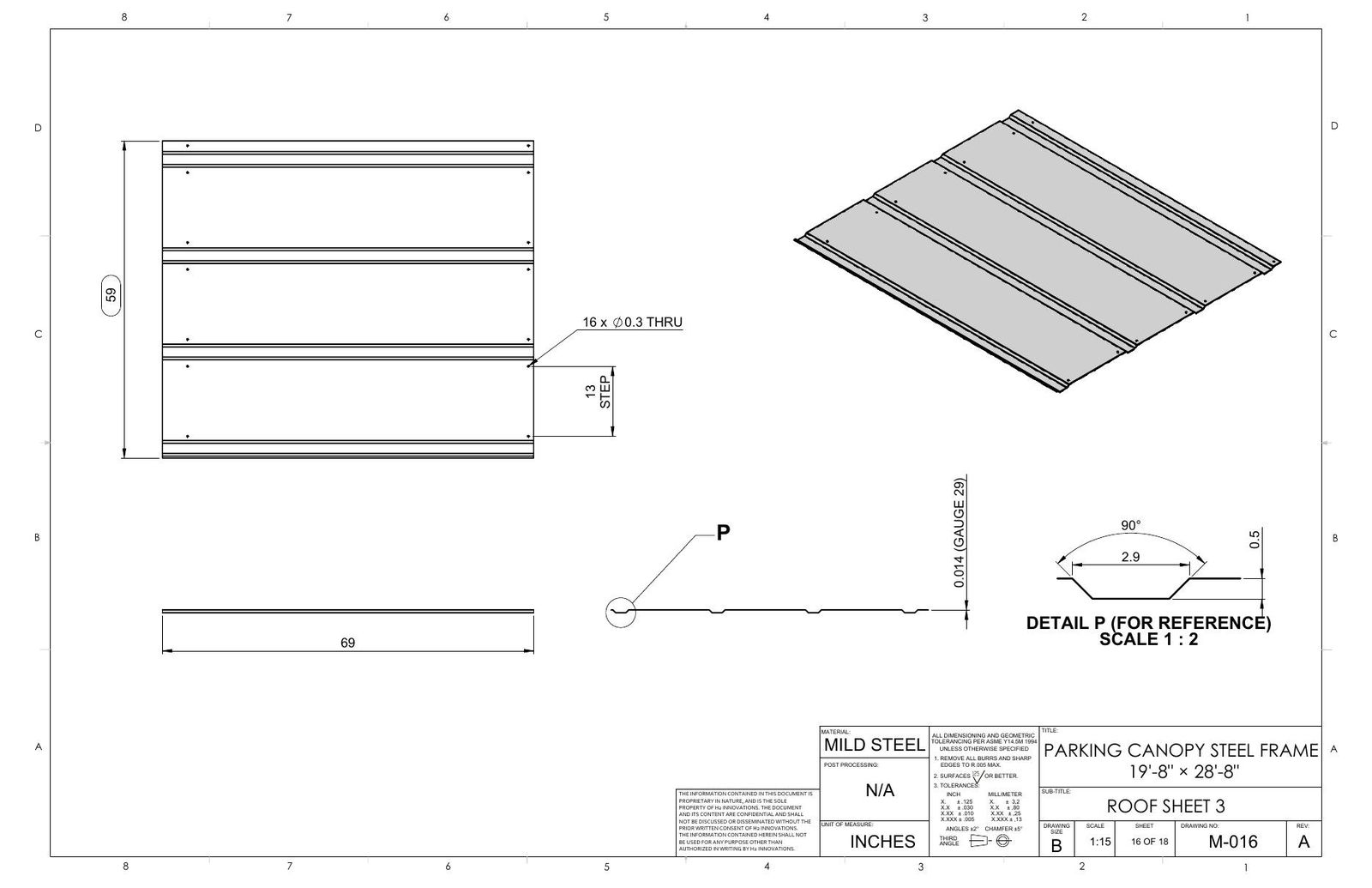
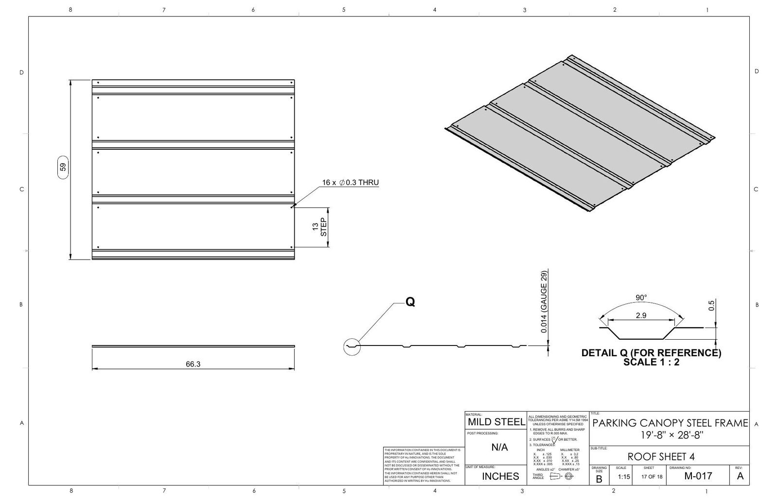
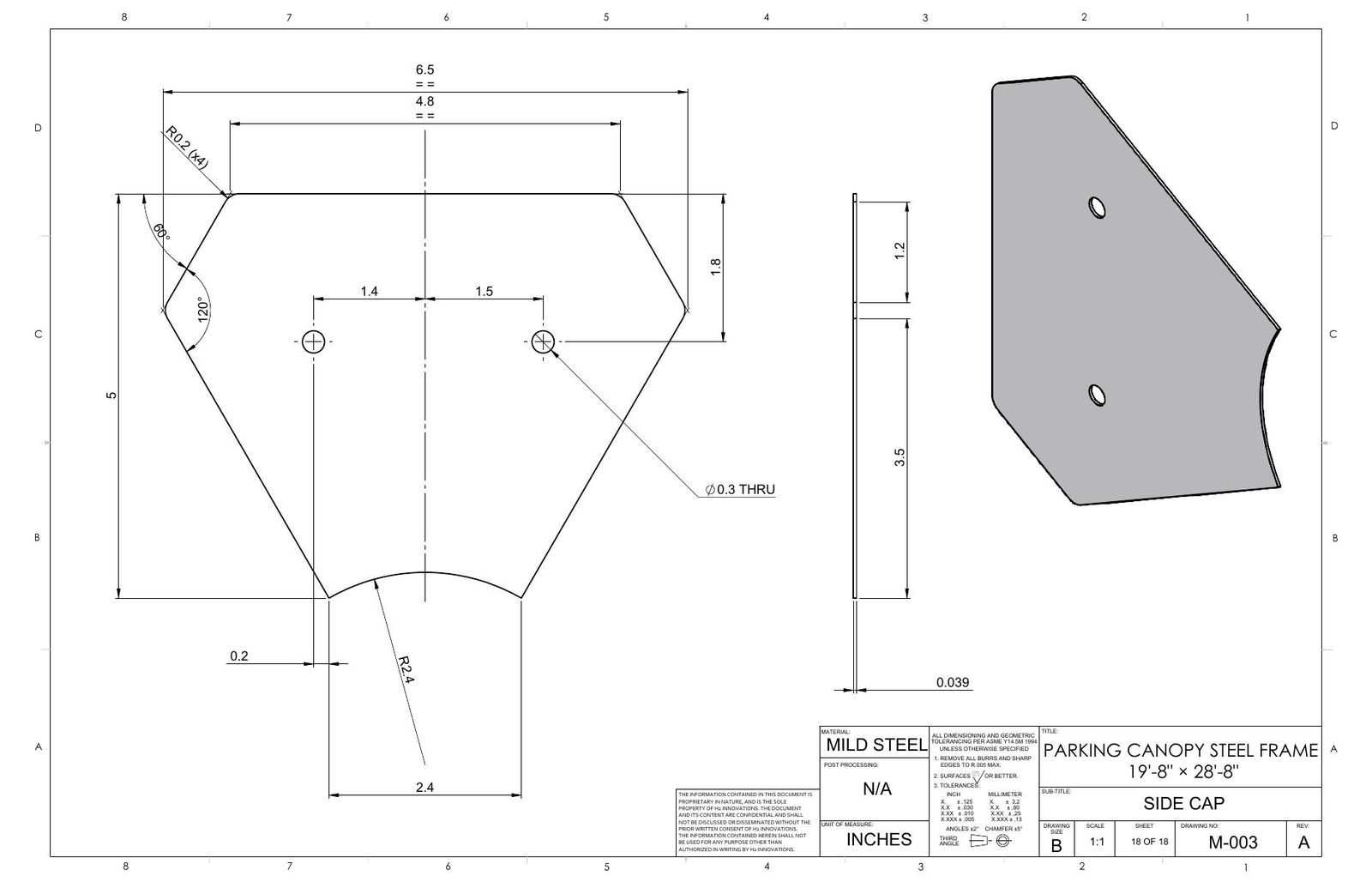
 RenderSolidWorks model
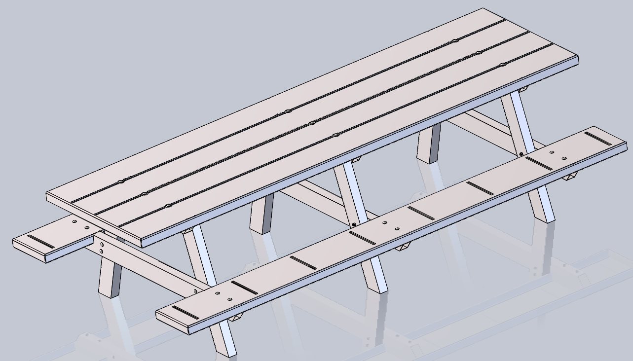
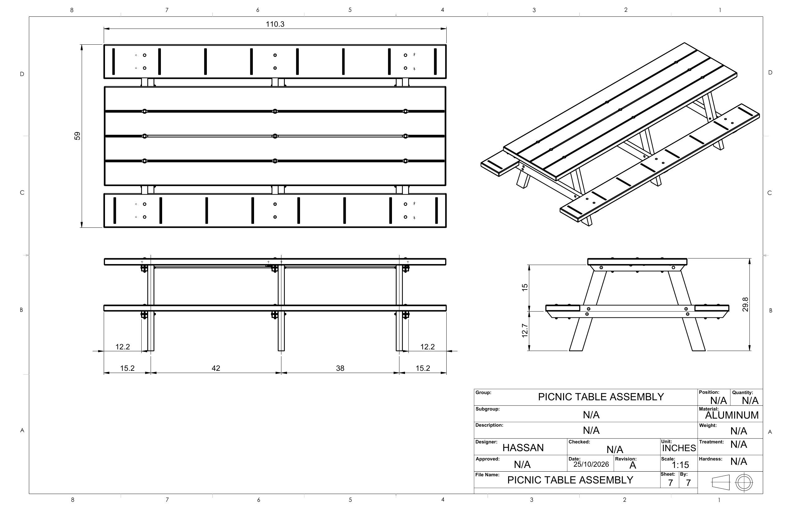
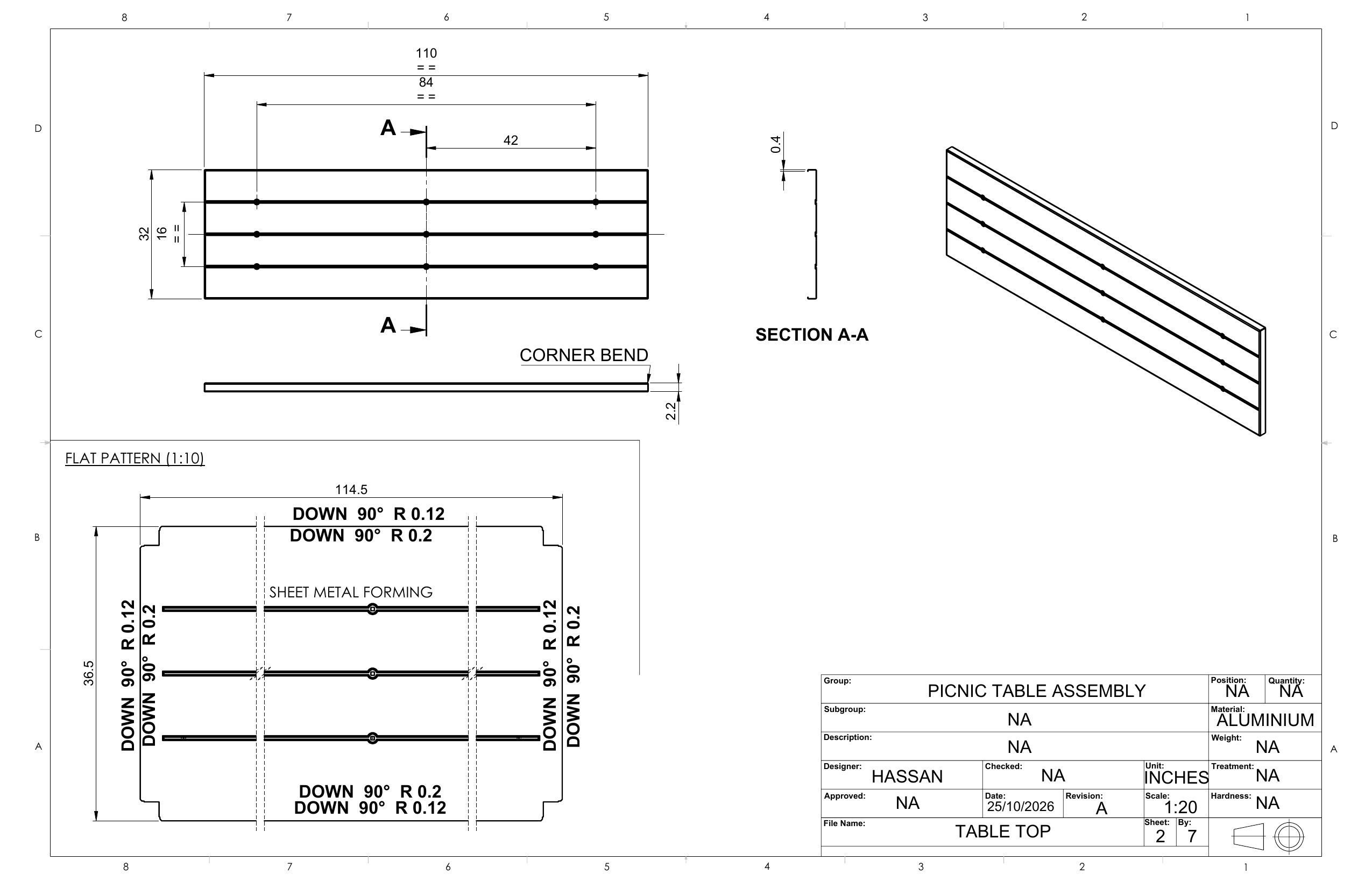
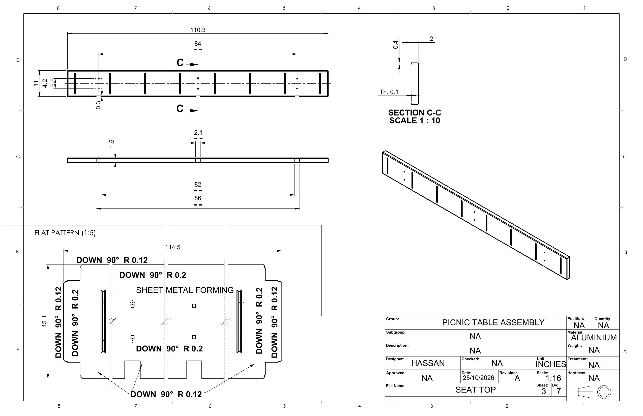
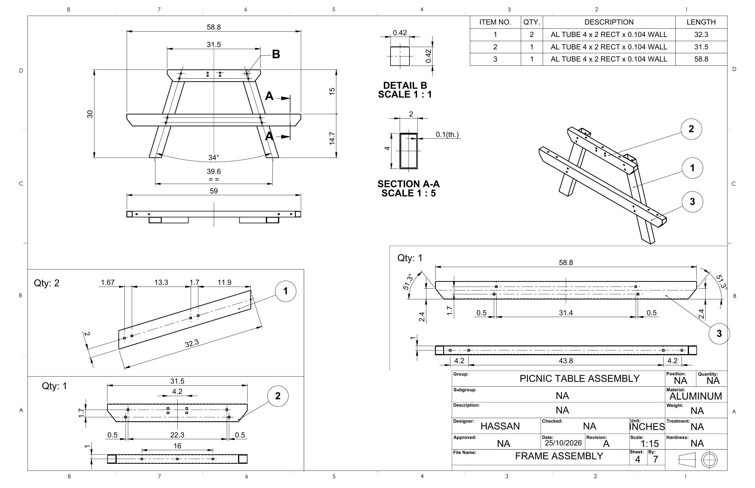
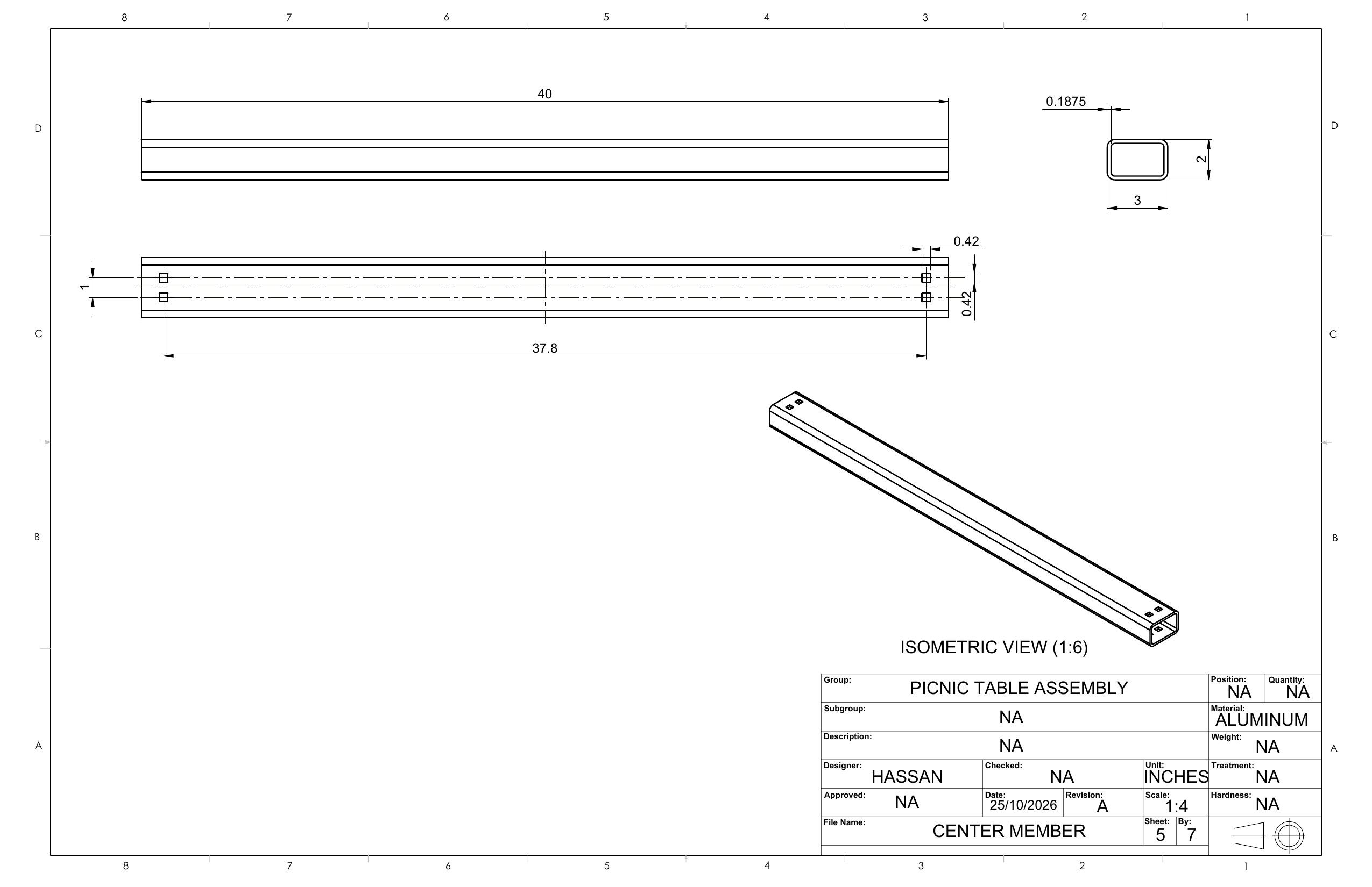
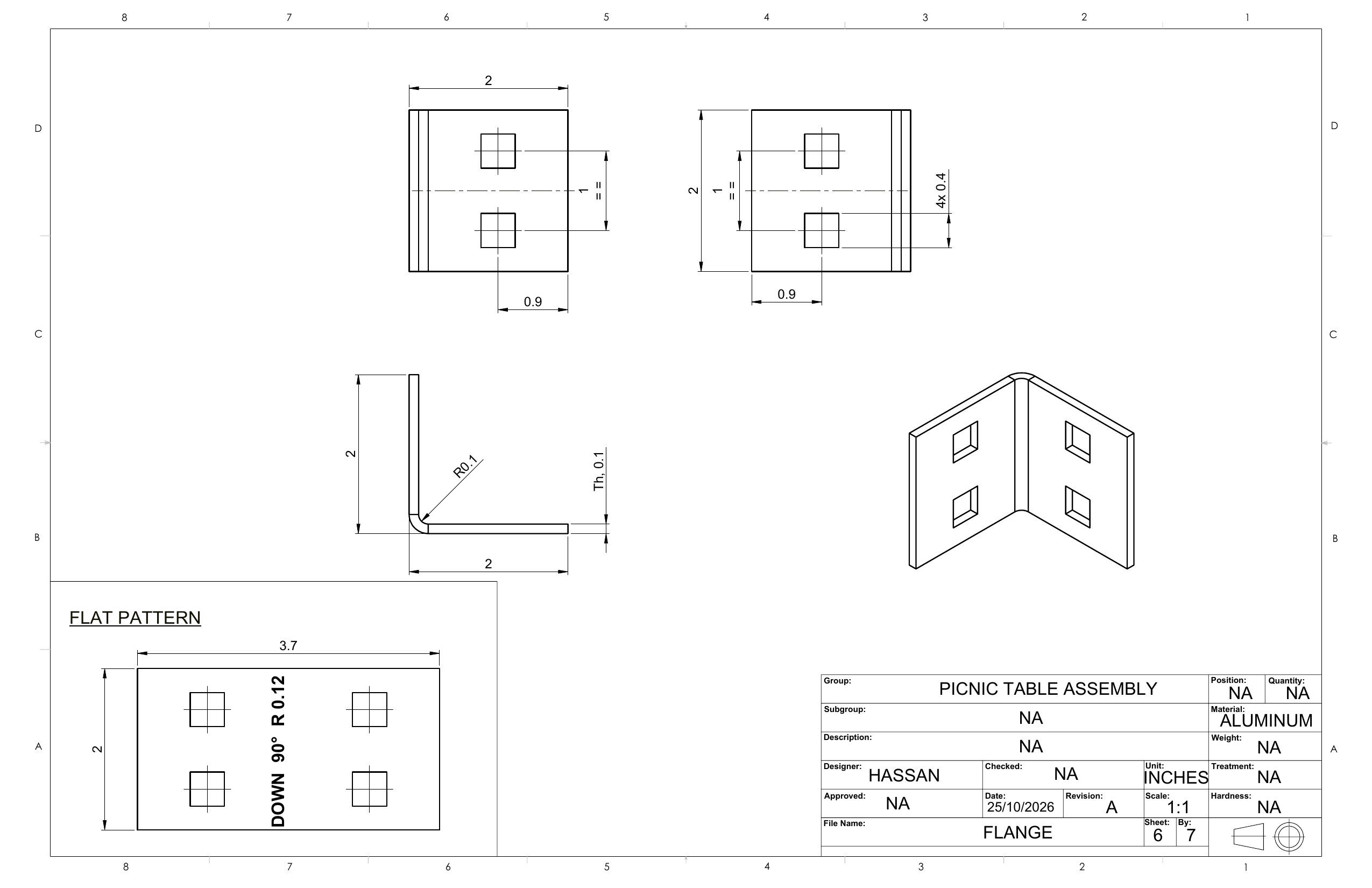
A full outdoor picnic table designed to be made from sheet metal and standard aluminium tube. The slatted table top and the two seats are formed from 2 mm sheet with bent edges, and bolted to A-frame legs made from rectangular tube. Each part has its own drawing, including the flat patterns with bend directions and radii. Drag the slider to change from the SolidWorks model to the render.
Use Previous / Next to flip through the sheets. Click a sheet to enlarge. Drawn in inches.
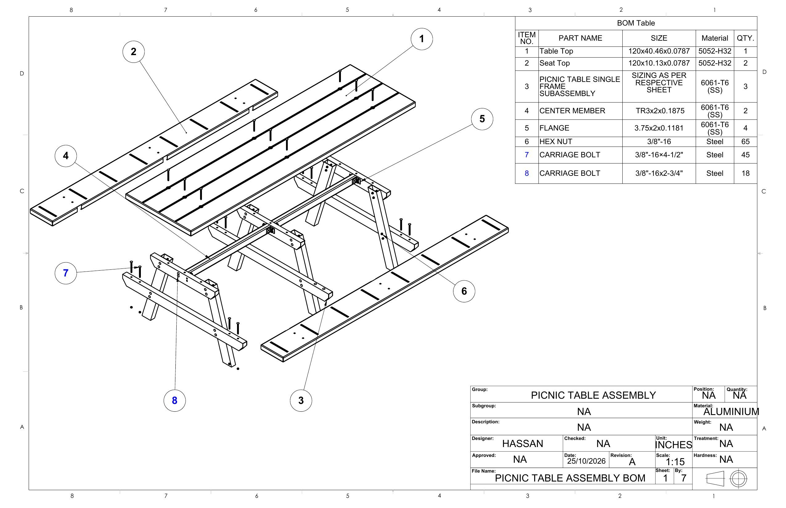
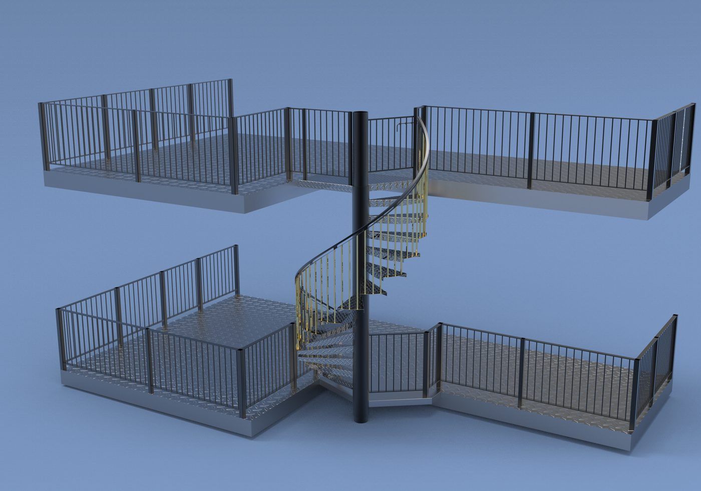
Spiral staircase connecting two railed platforms, modeled as a full assembly with railings and steel supports.
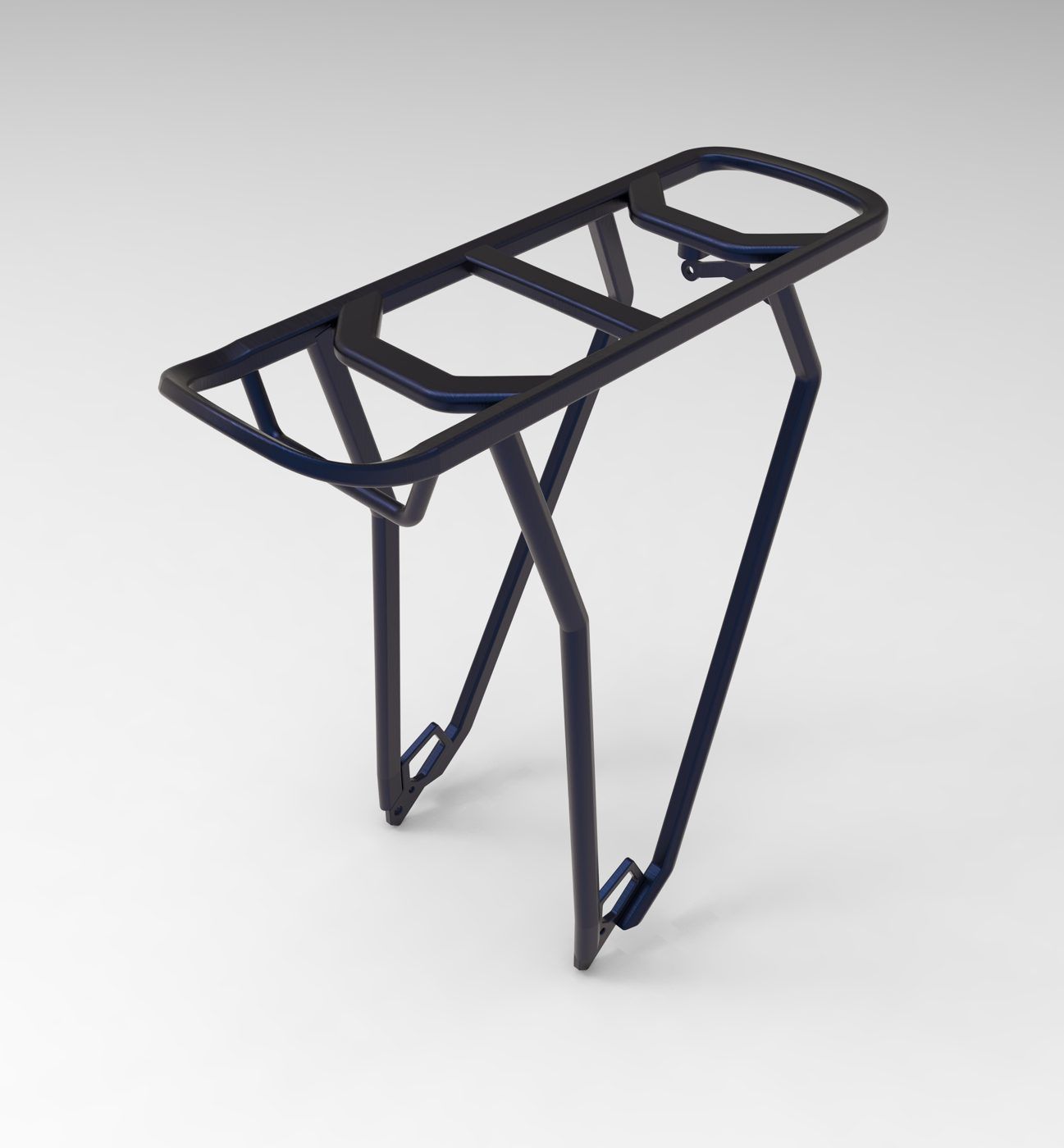
Bent-tube rack modeled for fabrication, with mounting points and frame geometry.
Clean, manufacturing-ready 2D profiles for cutting and fabrication.
Deliverables: CNC-ready DXF, plate and bracket profiles, nested layouts, fabrication kits.
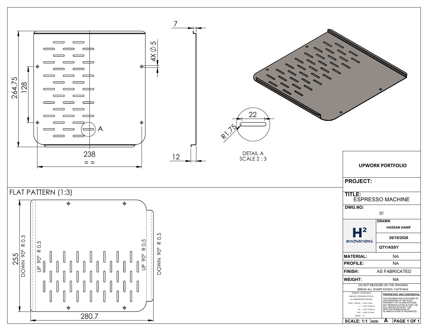
I designed the enclosure for an espresso machine in SolidWorks. This is one of its sheet-metal parts, a vented panel made to be CNC cut. The drawing gives the views, the slot and hole sizes, and a flat pattern with every bend marked up or down with its radius.
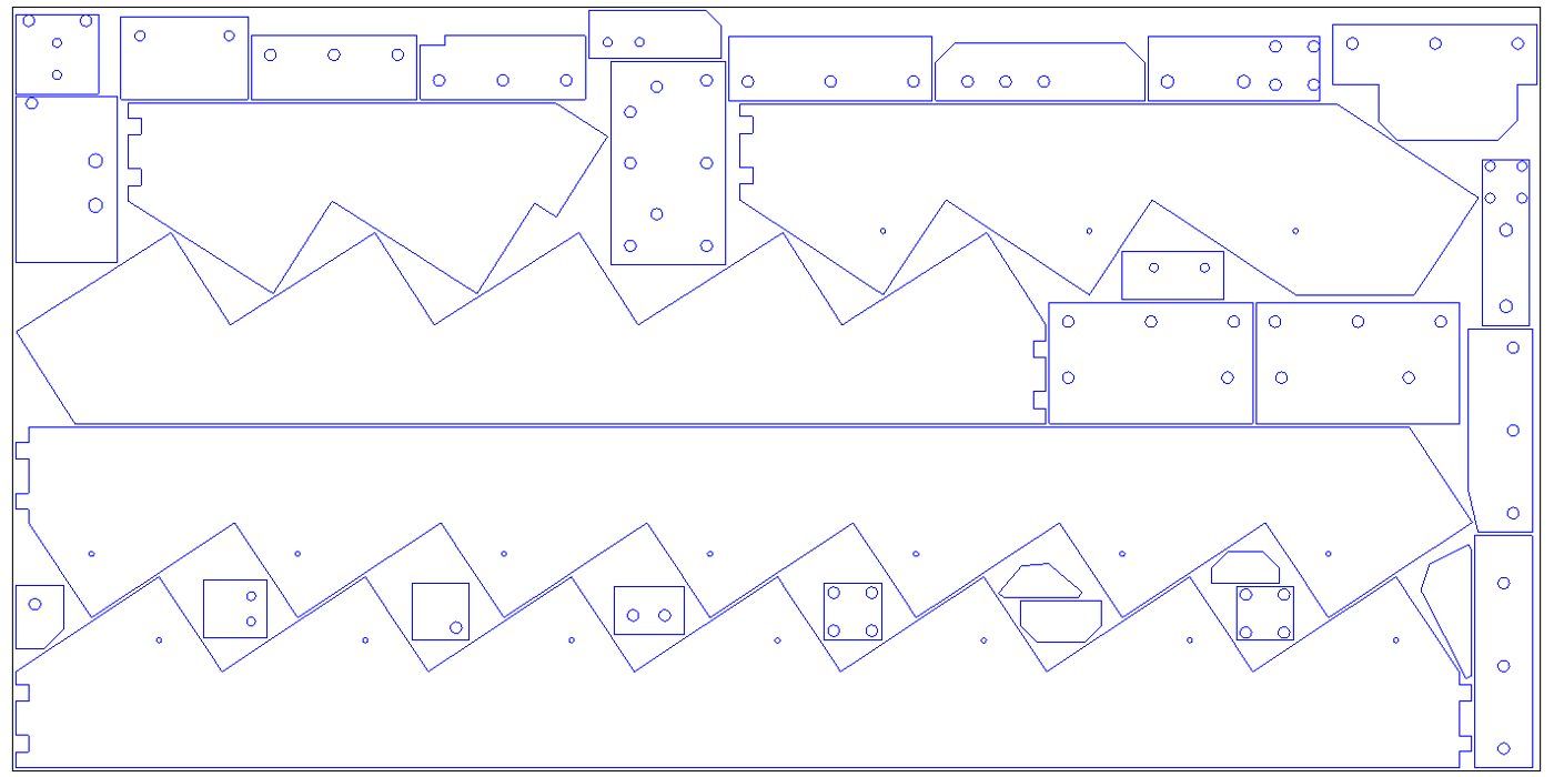
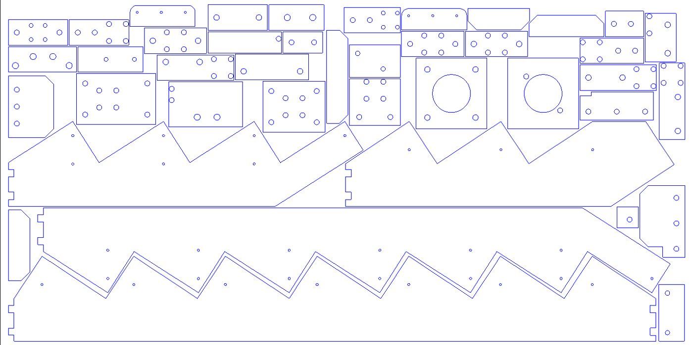
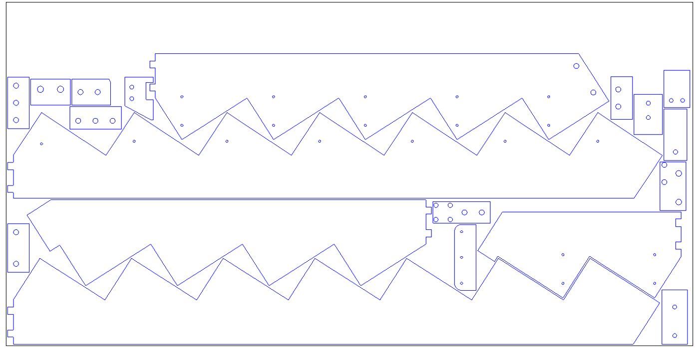
Plate profiles arranged to save material, prepared as clean DXF geometry for cutting.

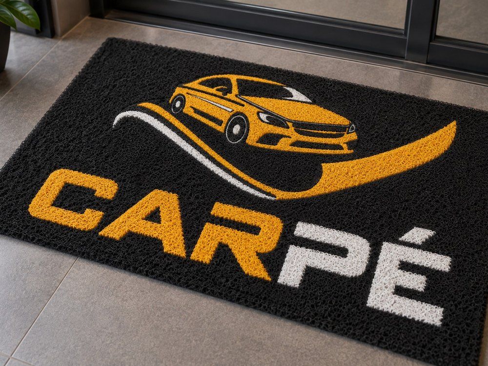
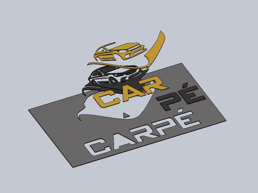


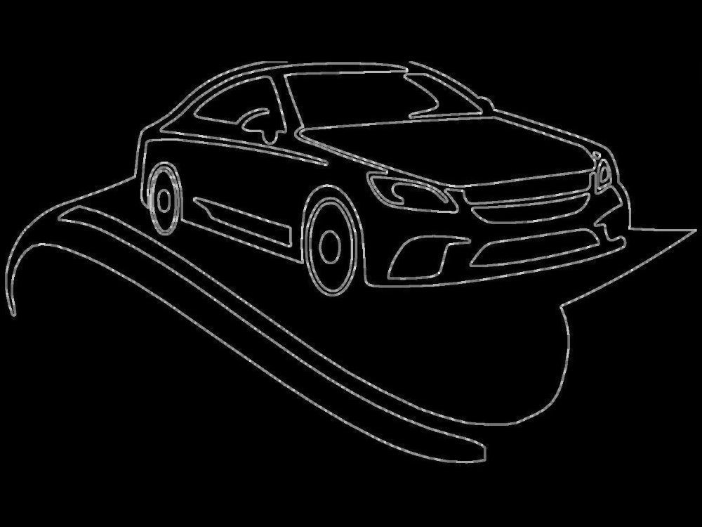
A logo mat for a company, made to be cut on a CNC knife cutter. I optimized the logo for cutting: every sharp corner with a radius under 5 mm was resolved to 5 mm. I then used the optimized logo to build the layers to be cut, applying design for manufacturing, and prepared them as DXF cutting files.
 Click the drawing to enlarge
A 90° round duct elbow built from 7 segments, 500 mm in diameter with a 750 mm bend radius, made from 2 mm sheet. I developed each segment into a flat pattern (1562.52 mm long, 263.3 mm wide) with a rip cut, ready to export as DXF for cutting. The sheet metal model and the drawing are made in SolidWorks.
Analysis that supports design decisions.
Includes: static structural FEA, stress and deformation, factor of safety, basic CFD support.
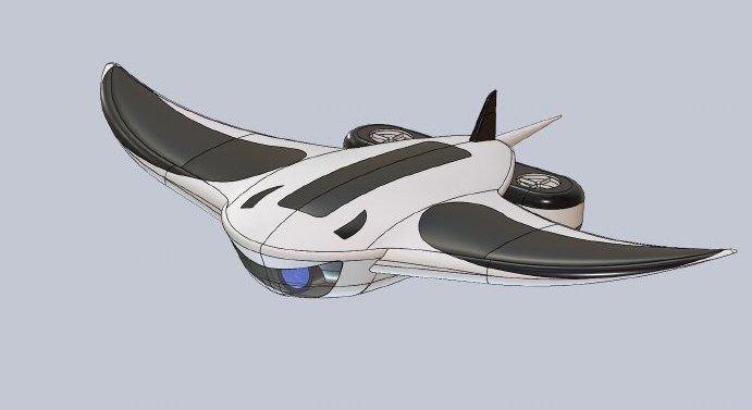
Surface-modeled drone concept, with CFD and structural analysis to support design decisions. Water flow at 3 m/s was simulated around the body, then the shell was checked structurally in ANSYS.
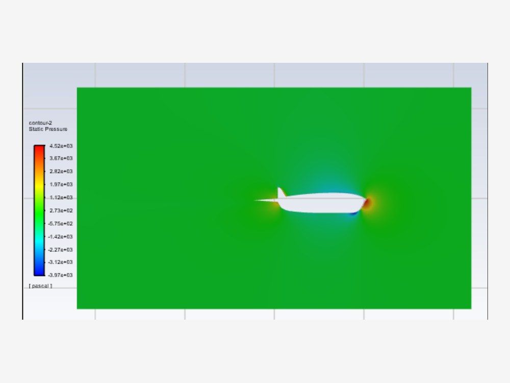
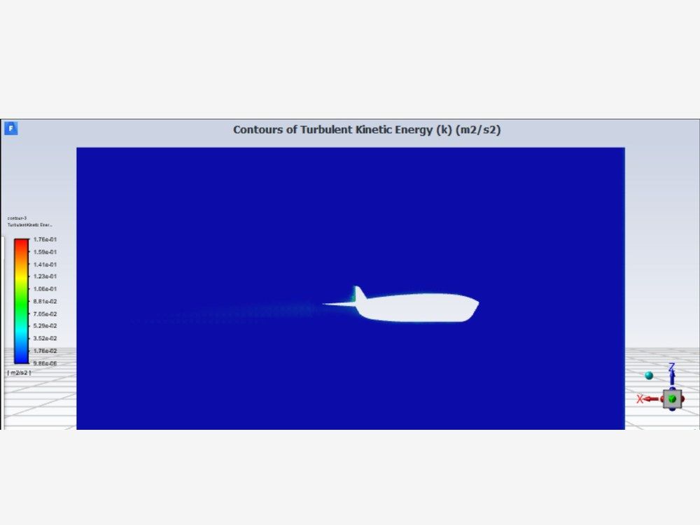
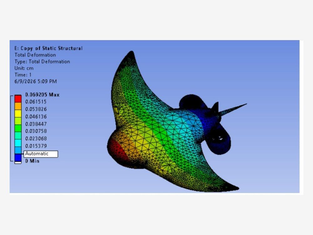
CFD setup: 2.085 m length, 0.7 m² reference area, water at 998 kg/m³. Drag splits into 288 N pressure and 35 N viscous. Pressure peaks at the nose, and turbulence is confined to a thin wake. Preliminary results.
Structural design, chassis packaging, load-bearing components, and FEA-based evaluation.
Preliminary analysis results, not structural certification.
Professional drawings for manufacturing, inspection, and fabrication.
Deliverables: dimensioned drawings, GD&T, section and detail views, assembly drawings, BOM, PDF and DWG.
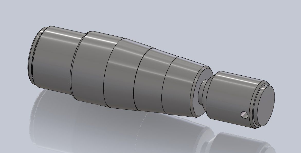
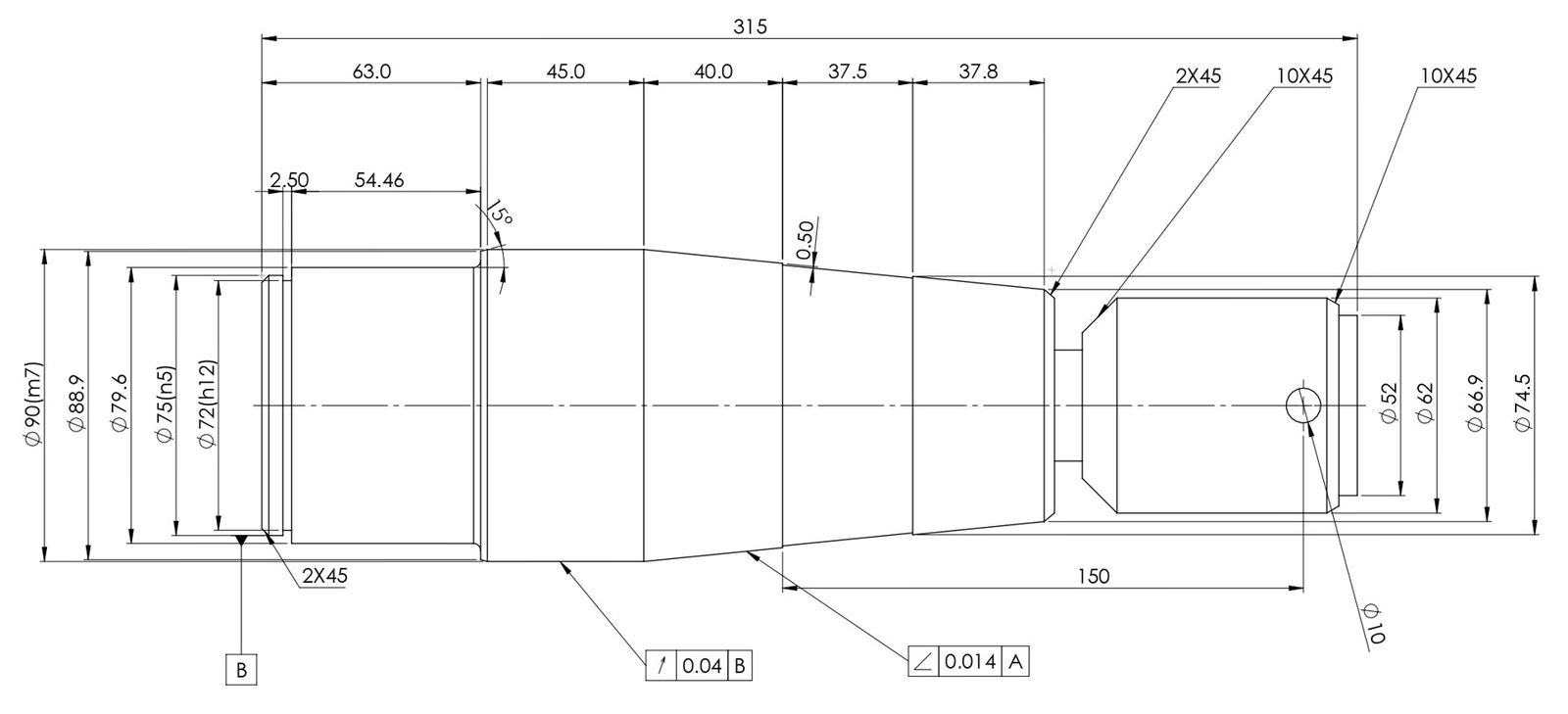
A stepped shaft modeled in 3D, with a fully dimensioned drawing: fit tolerances (m7, n5, h12), runout and angularity controls with datums, chamfers, and a cross hole.
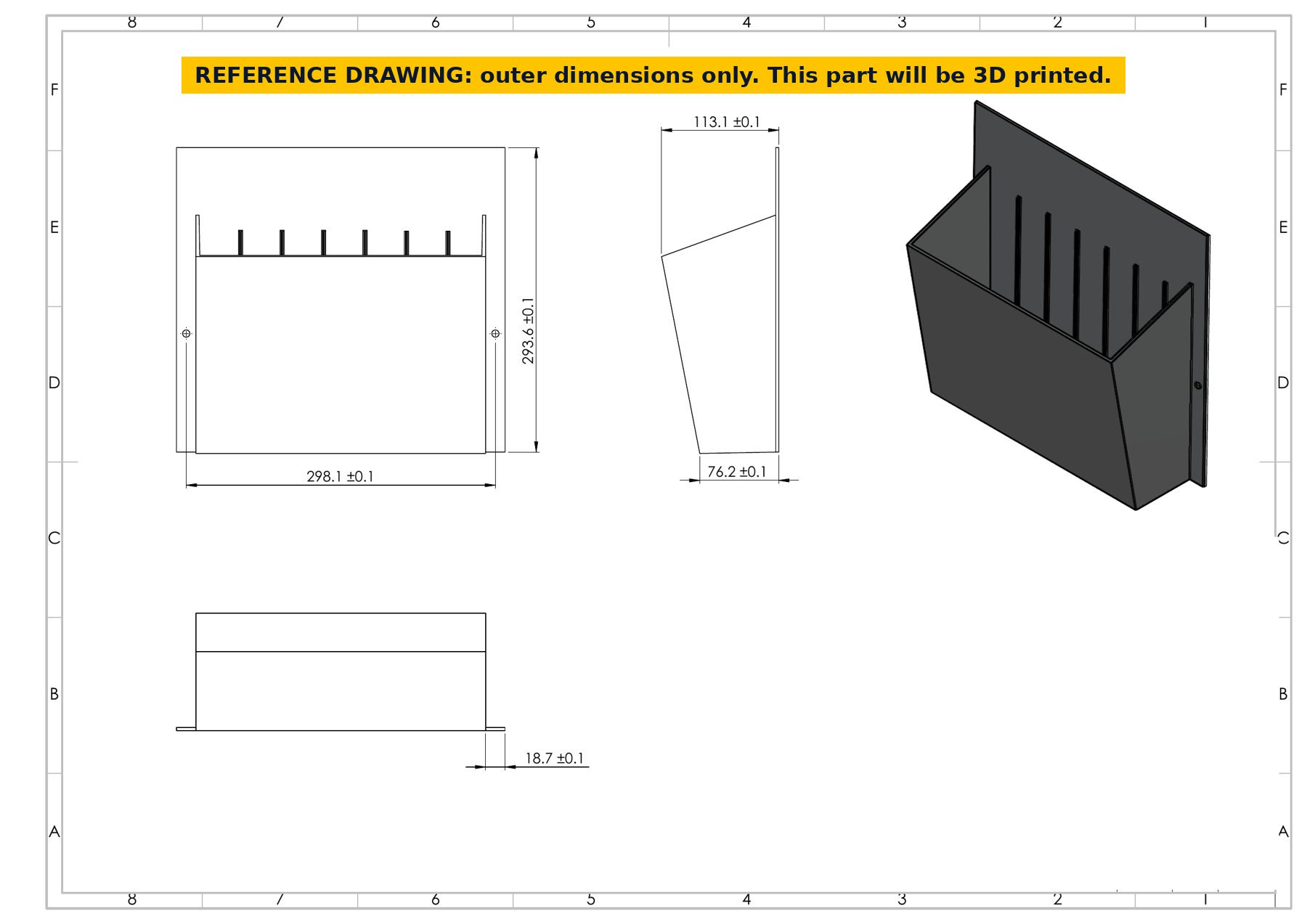
The first concept needed three to four different injection molds. I kept the overall ladder and rebuilt it from standard parts, so tooling drops to one optional mold.
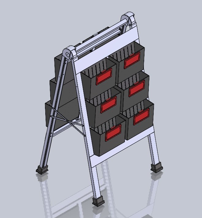
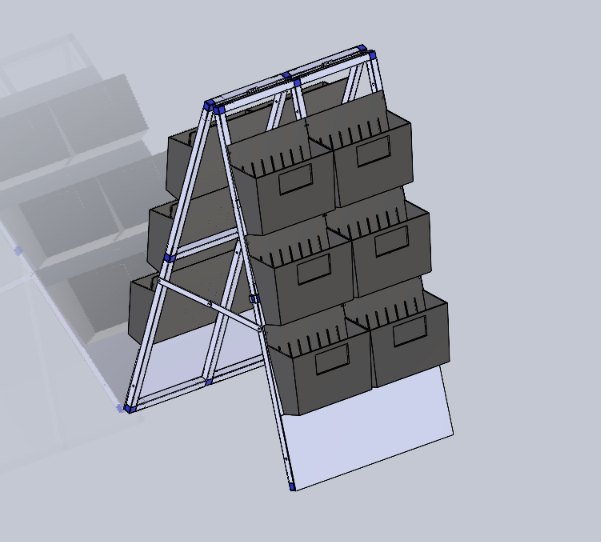
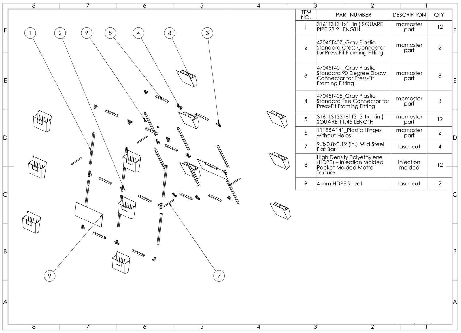
| Part | Qty | Route |
|---|---|---|
| Square tube, 1 × 1 in., 23.2 long | 12 | Standard part |
| Square tube, 1 × 1 in., 11.45 long | 12 | Standard part |
| Press-fit 90° elbow connector | 8 | Standard part |
| Press-fit tee connector | 8 | Standard part |
| Press-fit cross connector | 2 | Standard part |
| Plastic hinge | 2 | Standard part |
| Mild-steel flat bar, 9.3 × 0.8 × 0.12 in. | 4 | Laser cut |
| HDPE sheet, 4 mm | 2 | Laser cut |
| HDPE pocket | 12 | Injection molded or 3D printed |
Click a drawing to enlarge. The pocket drawing is a reference only, with outer dimensions, because that part will be 3D printed.
Practical product designs built around manufacturing and assembly needs.
Includes: concept design, DFM and DFA, prototype-ready models, mechanisms and motion studies (linkage and pivot arrangement, assembly integration, clearance checks).
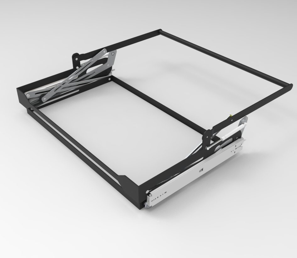
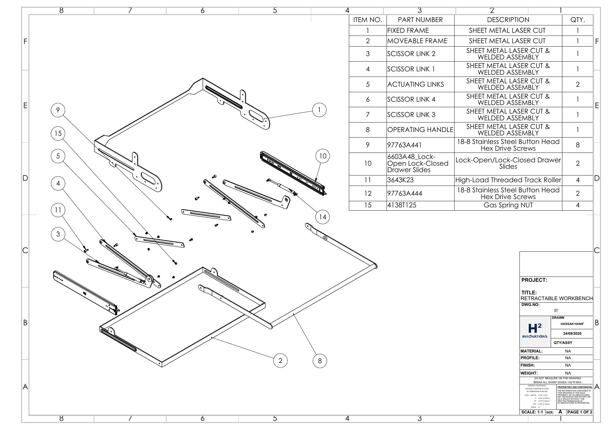
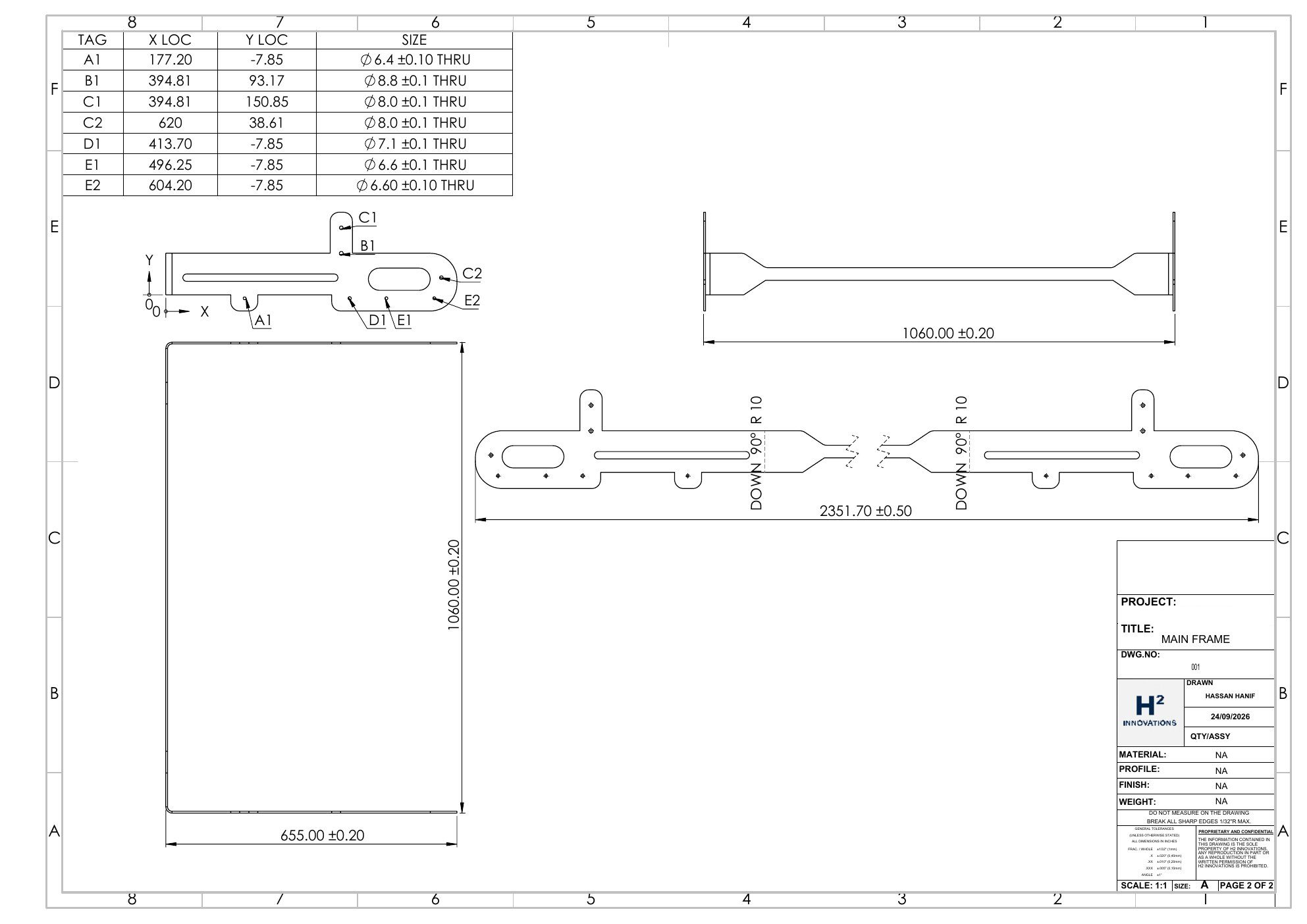
A workbench frame that slides out and lifts on scissor links. A moveable frame rides on drawer slides and track rollers, with gas springs to carry the load and an operating handle to move it. The frames and links are laser-cut sheet metal and welded assemblies. I modeled the mechanism, checked the motion, and drew every part for manufacture.
Use Previous / Next to flip through the sheets. Click a sheet to enlarge. Hole positions and sizes are tabulated on the frame drawing.
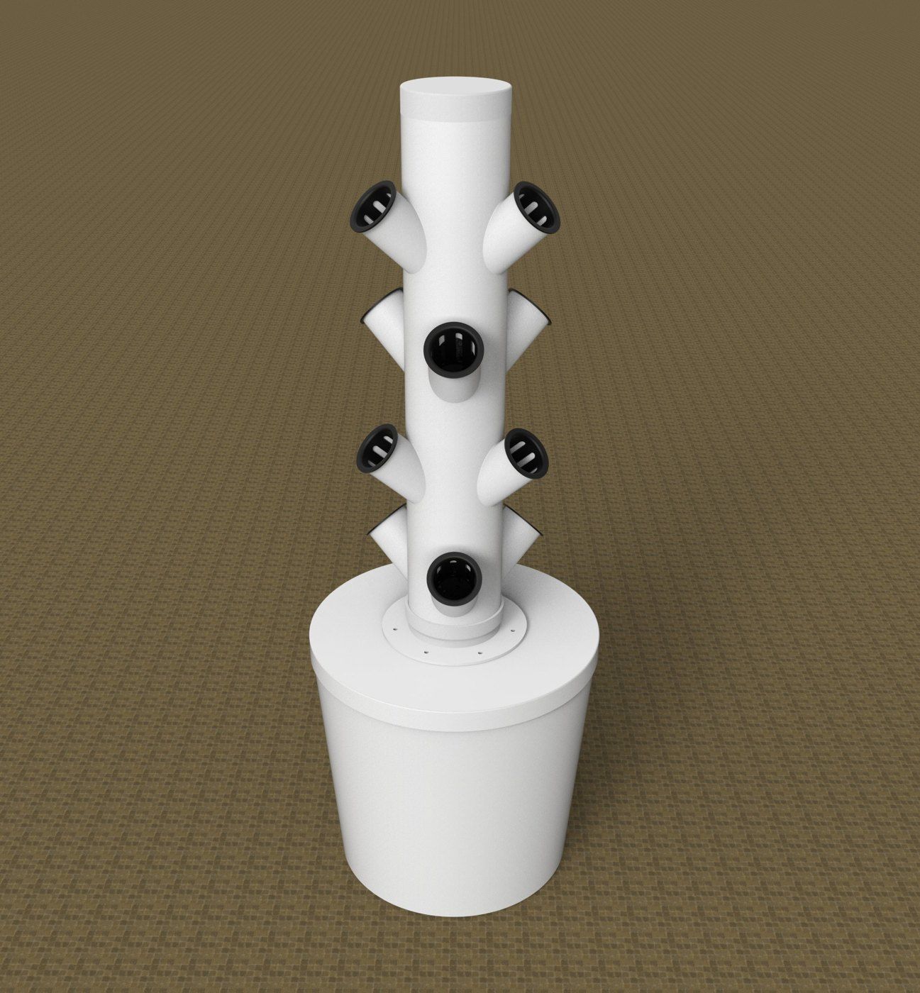
An indoor tower for growing leafy vegetables with less water. Modeled as a full assembly: base, central column, angled planter pockets, baskets, and flanges.
CAD models prepared for additive manufacturing and physical prototypes.
Includes: STL export, design adjustments for printing, clearance and fit tuning, assembly checks, iterations.
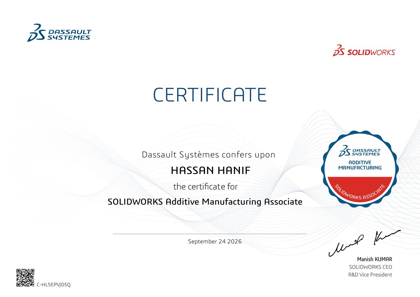
Certified: SOLIDWORKS Additive Manufacturing Associate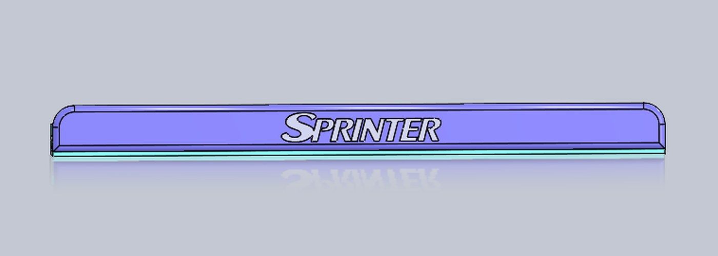
 Installed prototypeSolidWorks model
A custom dashboard iPad mounting system built as a two-part assembly. The L-part slides into the F-part along a guided path and locks with built-in ratchet teeth, so no screws or nuts are needed. Clearances were tuned for FDM printing and checked on real printed prototypes. Drag the slider to compare the prototype with the CAD model.
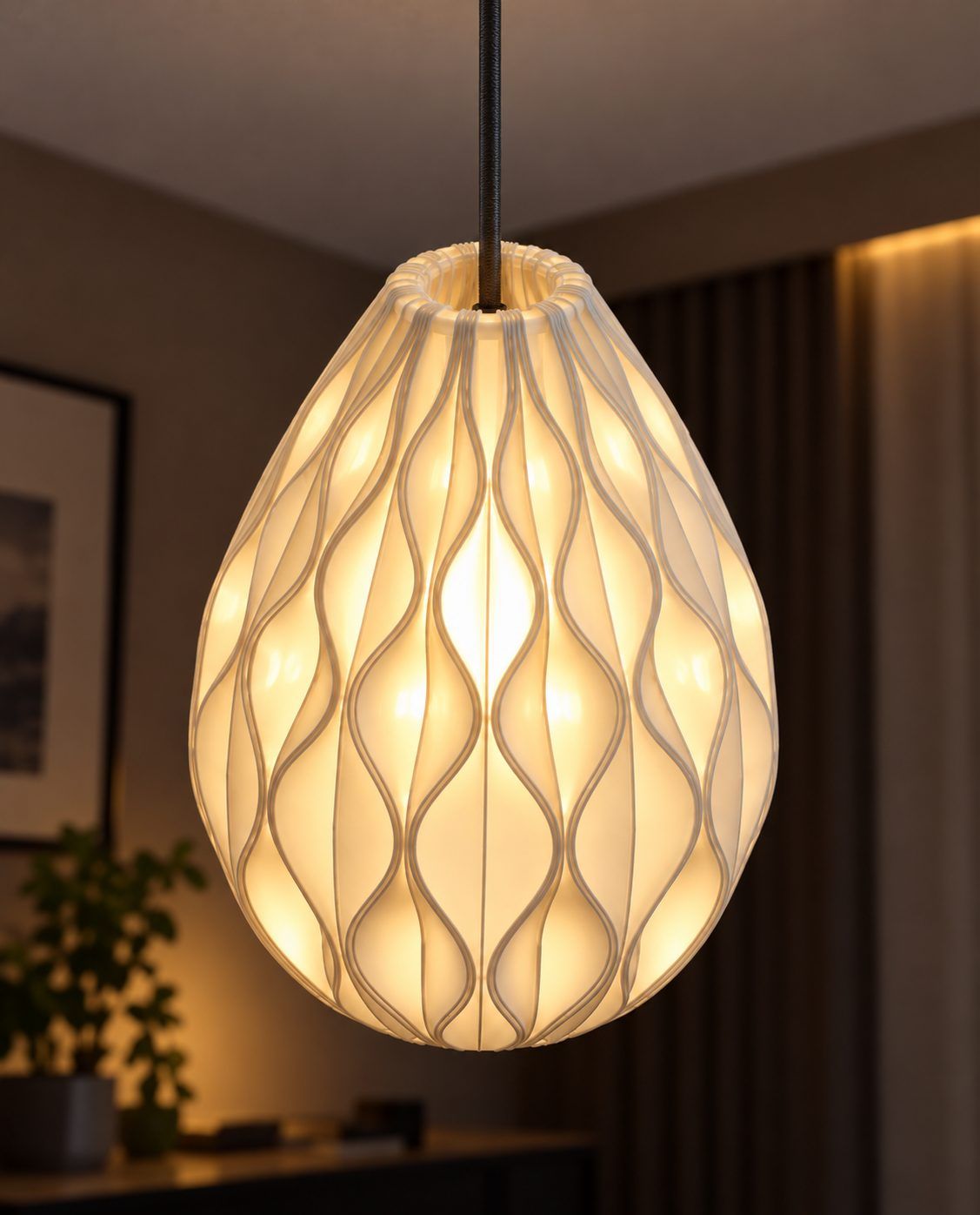
A pendant lamp with a lattice shade, designed for 3D printing.
Sketches, reference images, and existing geometry turned into accurate 3D models.
Deliverables: parametric parts, assemblies, exploded views, STEP and STL exports.
Certified: SOLIDWORKS Design Professional (CSWP)Sheet metal components and assemblies suited to manufacturing.
Includes: enclosures, brackets, panels, flat patterns, bend layouts, DXF exports.
Simulation results depend on geometry, material data, boundary conditions, contacts, and mesh quality. Critical designs require appropriate engineering validation.
Official certificates issued by Dassault Systèmes. Click a certificate to enlarge it.
Dassault Systèmes · May 2026
Dassault Systèmes · September 2026
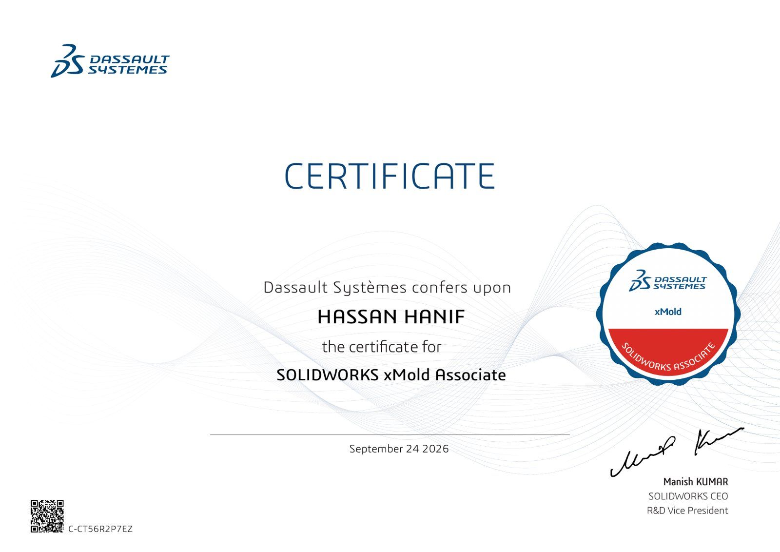
Dassault Systèmes · September 2026
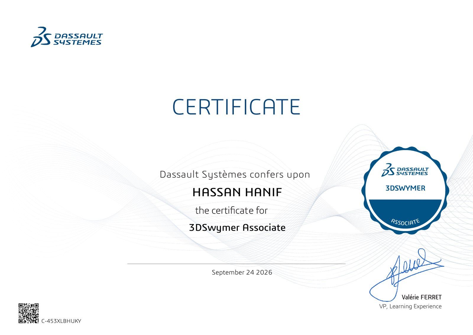
Dassault Systèmes · September 2026
Review your concept, files, dimensions, manufacturing needs, and application.
Create or refine the CAD model for function, geometry, material, and assembly.
Check dimensions, clearances, interfaces, and manufacturability, with simulation where needed.
Produce drawings, DXF files, BOM, and exchange formats.
Receive organized project files and agreed revisions.
Designs informed by mechanical engineering principles.
Attention to fabrication methods, tolerances, and assembly.
CAD models and documentation suited to your workflow.
One component, a complete assembly, or ongoing engineering tasks.
Structured requirements, deliverables, and revision discussions.
Design work tailored to your technical and manufacturing requirements.
Mechanical design, CAD modeling, product development, reverse engineering, and manufacturing documentation, helping product developers close the gap between an idea and a production-ready design.
Whether you are developing a new product, preparing parts for fabrication, reconstructing a component, or improving an assembly, send your sketches, reference images, CAD files, drawings, or a project description to get started.
Project:
Files are shared on request. I review each request and send the file to your email, usually within a day.